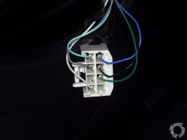
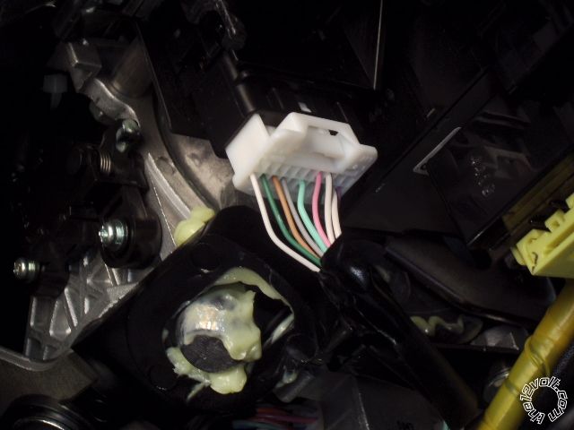
Setting up the 5906V with the idatalink acla d2d. Please review and give me any suggestions. thanks
H3/1 NC No Connection Not Used
H3/2 RED / BLACK (+) FUSED 12V ACC/STARTER INPUT White (50A) (+) @ ignition switch, White 8pin plug, blue pin 5
H3/3 PINK/BLACK (+) FLEX RELAY INPUT 87A Not Used
H3/4 PINK/WHITE (+) IGNITION 2 / FLEX RELAY OUTPUT Red + @ignition switch, White 8pin plug, blue pin 5
H3/5 RED (+) FUSED 12V IGNITION 1 INPUT White (50A) (+) @ ignition switch, White 8pin plug, blue pin 5
H3/6 GREEN (+) STARTER INPUT (KEY SIDE) Yellow (+) @ ignition switch, white 8 pin plug, Green pin 7
H3/7 VIOLET (+) STARTER OUTPUT (CAR SIDE) Yellow (+) @ ignition switch, white 8 pin plug, Green pin 7
H3/8 ORANGE (+) ACCESSORY OUTPUT Orange (+) @ ignition switch, white 8 pin plug, Gray pin 2
H3/9 RED / WHITE (+) FUSED 12V IGNITION 2 / FLEX RELAY White (50A) (+) @ignition switch, White 8pin plug, blue pin 5
H3/10 PINK (+) IGNITION 1 INPUT/OUTPUT Blue (+) @ ignition swith, white 8 pin plug, Black pin 8 + idatalink Pink ingnition(+) wire
Here is the Viper H2 connections :
Viper 5906v Harness 2
AUX/Shutdown/Trigger, 24-pin
H2/1 (-) Ignition 2 / Flex Output .2A Pink/White Not Used
H2/2 (-) 2nd Status / Rear Defogger Output .2A Blue/White Not Used
H2/3 (-) Trunk Release Output .2A RED / White Not used
H2/4 (-) Dome Light Output .2A BLACK / YELLOW Not Used
H2/5 (-) Status Output .2A Dark Blue not Used
H2/6 (-) Aux 3 Output .2A WHITE/ Black Not Used
H2/7 (-) Aux 1 Output .2A WHITE/ Violet Not Used
H2/8 (-) Aux 4 Output .2A ORANGE / Black Not Used
H2/9 (-) Hood Pin Input (Normally On or Normally Off) Gray Not Used H2/10 (-) Trunk Pin / Instant Trigger Input Blue Not Used
H2/11 Activation Input WHITE/ Blue Not Used
H2/12 Tachometer Input Violet/White To idatalink PURPLE / white Tach output
H2/13 (-) Neutral Safety / Parking Brake Input BLACK/ White Not Used (automatic)
H2/14 (-) Factory Alarm Disarm Output .2A GREEN/ Black Not Used
H2/15 (-) Door Input Green Not Used
H2/16 (-) Horn Honk Output .2A BROWN / Black Not Used
H2/17 (-) Ignition 1 Output .2A Pink Not Used
H2/18 (+) Door Input Violet Not Used
H2/19 (-) Aux 2 Output.2A Violet/Black Not Used
H2/20 (+) Brake Shutdown Input Brown To Idatalink Orange brake status output
H2/21 (-) Starter Output .2A Violet / YELLOW Not Used
H2/22 (-) Diesel Wait to Start Input Gray/Black Not Used
H2/23 (-) Accessory Output .2A Orange Not Used
H2/24 (-) Factory Alarm Arm Output .2A GREEN / WHITE Not Use
All that is left is the H1 harness :
Main Harness (H1), 6-pin connector
H1/1 RED (+)12VDC CONSTANT INPUT White (50A) (+) @ ignition switch, White 8 pin plug, Blue pin 5
H1/2 BLACK (-) CHASSIS GROUND Chassis Ground
H1/3 BROWN (+) SIREN OUTPUT Viper siren
H1/4 WHITE/ BROWN PARKING LIGHT ISOLATION Not Used
H1/5 WHITE PARKING LIGHT OUTPUT To Tundra White 20 pin plug, Biege, pin 18
H1/6 ORANGE (-) 500mA GWA OUTPUT Not Used
** Set Viper Parking Light Jumper/Fuse to (-)
ADS hook ups
d2d
WHITE/ Black - SIL (Data) Vehicle side to Tundra white 12 pin plug, Blue pin 10
WHITE/ Red - SIL (Data) Connector side to Tundra White 12 pin plug, Blue pin 10
BROWN / Red - CANH to Tundra White 16 pin plug, Purple pin 6
BROWN / Yellow - CANL to Tundra White 16 pin plug, White pin 14
ORANGE / Black - Immobilizer to Tundra Whte 16 pin plug, Biege pin 7
Pink ingnition to tundra ignition , Black pin 6
Green to Viper Violet/White
 Printable version


