the12volt.com spacer
icon

relay diagram planning advice needed


Post ReplyPost New Topic
< Prev Topic Next Topic >
defnu 
Member - Posts: 15
Member spacespace
Joined: June 12, 2009
Location: California, United States
Posted: June 12, 2009 at 12:41 PM / IP Logged  

hello.

i'm working on removing key cylinders for my doors (completed) and ignition.

i already have a keyless entry alarm system that i had to learn to install myself.  my end goal is to learn about wiring basics and relays are where i'm at right now. i wired the relays to my door locks but i guess that's not enough relay work for me to remember by heart.

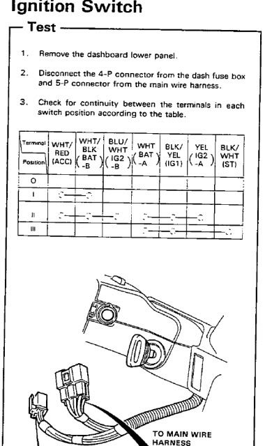
ANYWAYS! below is a diagram of my ignition system.  i have a diagram for the starter button (does not incorporate a connection with WHT (BAT -a).

i am left with wiring the ACCssories (I) and the ON (II) switch to a three option toggle (off, option a, option b)

how can i acheive this with the least amount of relays? thanks for any input.

[IMG]https://i272.photobucket.com/albums/jj173/defnu/IGN.jpg[/IMG]

hello.
defnu 
Member - Posts: 15
Member spacespace
Joined: June 12, 2009
Location: California, United States
Posted: June 12, 2009 at 1:04 PM / IP Logged  

relay diagram planning advice needed -- posted image.

hello.
defnu 
Member - Posts: 15
Member spacespace
Joined: June 12, 2009
Location: California, United States
Posted: June 12, 2009 at 1:05 PM / IP Logged  
sorry for my noob posts, but if you have an idea just label the wires A-G
hello.
KPierson 
Platinum - Posts: 3,527
Platinum spaceThis member consistently provides reliable informationspace
Joined: April 14, 2005
Location: Ohio, United States
Posted: June 12, 2009 at 1:26 PM / IP Logged  

You should be able to do it with 5 relays (one relay for each switched wire) and 9 diodes.  The diodes will prevent backfeeding from position to position.

relay coil A = WHITE/ black

relay coil B = WHITE/ blue
relay coil C = BLACK / YELLOW 
relay coil D = yellow
relay coil E =  BLACK/ white

So -

Switch Output 1 --> Diode --> relay coil A

Switch Output 2 --> Diode --> relay coil A

Switch Output 2 --> Diode --> relay coil B
Switch Output 2 --> Diode --> relay coil C
Switch Output 2 --> Diode --> relay coil D
Switch Output 2 --> Diode --> relay coil B

Switch Output 3 --> Diode --> relay coil C

Switch Output 3 --> Diode --> relay coil E

Then you would just need to make sure the correct output is wired to the correct battery source.

Kevin Pierson
defnu 
Member - Posts: 15
Member spacespace
Joined: June 12, 2009
Location: California, United States
Posted: June 12, 2009 at 2:06 PM / IP Logged  
KPierson wrote:

You should be able to do it with 5 relays (one relay for each switched wire) and 9 diodes.  The diodes will prevent backfeeding from position to position.

relay coil A = WHITE/ black

relay coil B = WHITE/ blue
relay coil C = BLACK / YELLOW 
relay coil D = yellow
relay coil E =  BLACK/ white

So -

Switch Output 1 --> Diode --> relay coil A

Switch Output 2 --> Diode --> relay coil A

Switch Output 2 --> Diode --> relay coil B
Switch Output 2 --> Diode --> relay coil C
Switch Output 2 --> Diode --> relay coil D
Switch Output 2 --> Diode --> relay coil B

Switch Output 3 --> Diode --> relay coil C

Switch Output 3 --> Diode --> relay coil E

Then you would just need to make sure the correct output is wired to the correct battery source.

nice, thanks! i've never worked with diodes but i'm going to look that up.  is there some kind of rating i should look for? i'll be reading up regardless, thanks much again!

hello.
KPierson 
Platinum - Posts: 3,527
Platinum spaceThis member consistently provides reliable informationspace
Joined: April 14, 2005
Location: Ohio, United States
Posted: June 12, 2009 at 4:54 PM / IP Logged  
1A diodes will be adequate for your application
Kevin Pierson
howie ll 
Pot Metal - Posts: 16,466
Pot Metal spacespace
Joined: January 09, 2007
Location: United Kingdom
Posted: June 13, 2009 at 2:05 AM / IP Logged  
Anyone thought about (possible) factory transponder, steering lock etc etc etc. Fun, possibly expensive, lots of extra wiring etc. etc.
defnu 
Member - Posts: 15
Member spacespace
Joined: June 12, 2009
Location: California, United States
Posted: June 13, 2009 at 2:44 PM / IP Logged  

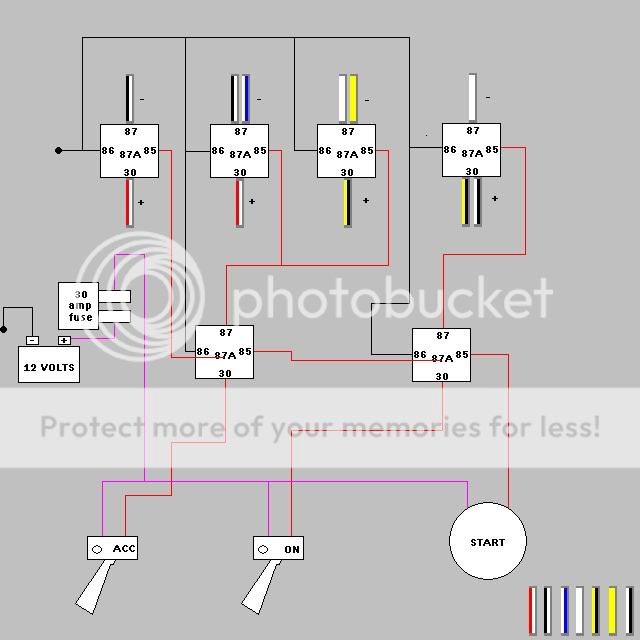
relay diagram planning advice needed -- posted image.

hopefully this will work. thanks for the conformation. 

i'm also in the market for a single toggle switch that can handle both "ACC" and "ON."  i'm just not sure what the tabs for wire mounting would look like.  would this switch be called a dpdt?

also, what websites are good for relays and switches? i'm in elk grove california and there is not anything local with a reasonable price.  the only thing radioshack had in stock were spst relays for $7.00 plus tax (CAlifornia) a piece!? i remember getting them for less than $5 from autozone and those came with pigtail harness' for the relay AND were spdt!

hello.
defnu 
Member - Posts: 15
Member spacespace
Joined: June 12, 2009
Location: California, United States
Posted: June 13, 2009 at 2:49 PM / IP Logged  
also, i don't know where to place the 1amp diodesrelay diagram planning advice needed -- posted image.
hello.
defnu 
Member - Posts: 15
Member spacespace
Joined: June 12, 2009
Location: California, United States
Posted: June 13, 2009 at 2:50 PM / IP Logged  

lol, i also don't know if thats the correct way to place the fuse or the correct fuse....im such a noob!

i did try my best to write out a clean diagram though.

hello.
Page of 3

  Printable version Printable version Post ReplyPost New Topic
You cannot post new topics in this forum
You cannot reply to topics in this forum
You cannot delete your posts in this forum
You cannot edit your posts in this forum
You cannot create polls in this forum
You cannot vote in polls in this forum

  •  
Search the12volt.com
Follow the12volt.com Follow the12volt.com on Facebook
Thursday, May 1, 2025 • Copyright © 1999-2025 the12volt.com, All Rights Reserved Privacy Policy & Use of Cookies
Disclaimer: *All information on this site ( the12volt.com ) is provided "as is" without any warranty of any kind, either expressed or implied, including but not limited to fitness for a particular use. Any user assumes the entire risk as to the accuracy and use of this information. Please verify all wire colors and diagrams before applying any information.

Secured by Sectigo
the12volt.com spacer
Support the12volt.com
Top
the12volt.com spacer