the12volt.com spacer
icon

How can I fix this circuit?


Post ReplyPost New Topic
< Prev Topic Next Topic >
eloshdesign 
Member - Posts: 15
Member spacespace
Joined: March 24, 2002
Location: United States
Posted: March 29, 2002 at 6:26 PM / IP Logged  
Please take a look at the attached diagram. The manual rocker switch was hooked up and worked fine. When I added the dual relay circuit (for remote control) the fuse at the switch would blow when I pressed up or down on the switch.
I can have either remote control or manual control, but not both at the same time. Looking at the diagram, why is this happening and how can I fix it so both methods can get along?
The pulse stretcher is not actually hooked up yet.
Thanks,
DarenHow can I fix this circuit? -- posted image.
the12volt 
Administrator - Posts: 3,957
Administrator spaceThis member has made a donation to the12volt.com. Click here for more info.spaceThis member has been recognized as an authority in Electrical Theory. Click here for more info.spaceThis member has been recognized as an authority in Mobile Audio and Video. Click here for more info.spaceThis member has been recognized as an authority in Mobile Security and Convenience. Click here for more info.spacespace
Joined: March 07, 2002
Location: Louisiana, United States
Posted: March 29, 2002 at 11:08 PM / IP Logged  

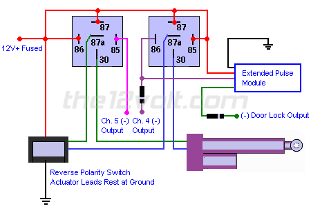
Hi eloshdesign, the fix is simple, you need to cut each lead from the switch to the actuator and connect 87a to the switch side of the respective actuator lead and connect 30 to the motor side of the respective actuator lead.

the12volt

the12volt 
Administrator - Posts: 3,957
Administrator spaceThis member has made a donation to the12volt.com. Click here for more info.spaceThis member has been recognized as an authority in Electrical Theory. Click here for more info.spaceThis member has been recognized as an authority in Mobile Audio and Video. Click here for more info.spaceThis member has been recognized as an authority in Mobile Security and Convenience. Click here for more info.spacespace
Joined: March 07, 2002
Location: Louisiana, United States
Posted: March 29, 2002 at 11:17 PM / IP Logged  

BTW, if you need me to draw a diagram of the workling circuit, just let me know.

the12volt

delosh 
Member - Posts: 4
Member spacespace
Joined: March 18, 2002
Location: United States
Posted: March 30, 2002 at 12:30 AM / IP Logged  
I would love a diagram. Could you please do one up for me?
Thanks,
Daren
delosh 
Member - Posts: 4
Member spacespace
Joined: March 18, 2002
Location: United States
Posted: March 30, 2002 at 8:31 AM / IP Logged  
I read it again today…it's much clearer now.
Note to self: Do not try to figure out electronic circuits AFTER the neighbors come over for drinks.
Thanks!
Daren
the12volt 
Administrator - Posts: 3,957
Administrator spaceThis member has made a donation to the12volt.com. Click here for more info.spaceThis member has been recognized as an authority in Electrical Theory. Click here for more info.spaceThis member has been recognized as an authority in Mobile Audio and Video. Click here for more info.spaceThis member has been recognized as an authority in Mobile Security and Convenience. Click here for more info.spacespace
Joined: March 07, 2002
Location: Louisiana, United States
Posted: March 30, 2002 at 10:49 AM / IP Logged  

Hi Daren, here ya go:

How can I fix this circuit? -- posted image.

Let me know if you need anything else.

the12volt

eloshdesign 
Member - Posts: 15
Member spacespace
Joined: March 24, 2002
Location: United States
Posted: March 30, 2002 at 12:24 PM / IP Logged  
Thanks for the diagram.
I wired it just like you have it in the above diagram, but the actuators don't move via the alarm remote. The manual switch works and the 30's light up my test light via the alarm remote (when the test light is grounded to the chassis). Are the actuators not getting ground somehow when activated vis the remote?
Thanks
the12volt 
Administrator - Posts: 3,957
Administrator spaceThis member has made a donation to the12volt.com. Click here for more info.spaceThis member has been recognized as an authority in Electrical Theory. Click here for more info.spaceThis member has been recognized as an authority in Mobile Audio and Video. Click here for more info.spaceThis member has been recognized as an authority in Mobile Security and Convenience. Click here for more info.spacespace
Joined: March 07, 2002
Location: Louisiana, United States
Posted: March 30, 2002 at 1:09 PM / IP Logged  

Hi eloshddesign, measure resistance to ground on each actuator lead at the actuators. If they are not resting at ground with nothing activated, then I'd suggest rewiring your switch so the actuators do rest at ground or even wire the switch to activate the coils of the relays to control the actuators.

the12volt

eloshdesign 
Member - Posts: 15
Member spacespace
Joined: March 24, 2002
Location: United States
Posted: March 30, 2002 at 1:15 PM / IP Logged  
Would it be possible to do another diagram that shows the above options? It's a little unclear to me about "resting at ground". Does that mean the switch needs to grounded all the time?
Thanks
the12volt 
Administrator - Posts: 3,957
Administrator spaceThis member has made a donation to the12volt.com. Click here for more info.spaceThis member has been recognized as an authority in Electrical Theory. Click here for more info.spaceThis member has been recognized as an authority in Mobile Audio and Video. Click here for more info.spaceThis member has been recognized as an authority in Mobile Security and Convenience. Click here for more info.spacespace
Joined: March 07, 2002
Location: Louisiana, United States
Posted: March 30, 2002 at 1:29 PM / IP Logged  

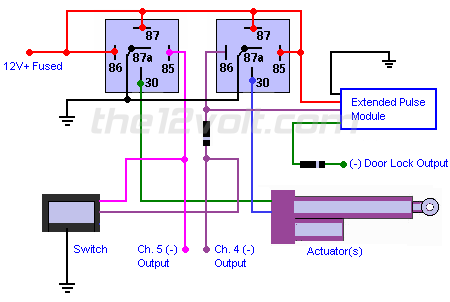
Here's a diagram showing the switch activatiing the coils of the relays to control the actuators.

How can I fix this circuit? -- posted image.

the12volt

Page of 2

  Printable version Printable version Post ReplyPost New Topic
You cannot post new topics in this forum
You cannot reply to topics in this forum
You cannot delete your posts in this forum
You cannot edit your posts in this forum
You cannot create polls in this forum
You cannot vote in polls in this forum

  •  
Search the12volt.com
Follow the12volt.com Follow the12volt.com on Facebook
Tuesday, June 17, 2025 • Copyright © 1999-2025 the12volt.com, All Rights Reserved Privacy Policy & Use of Cookies
Disclaimer: *All information on this site ( the12volt.com ) is provided "as is" without any warranty of any kind, either expressed or implied, including but not limited to fitness for a particular use. Any user assumes the entire risk as to the accuracy and use of this information. Please verify all wire colors and diagrams before applying any information.

Secured by Sectigo
the12volt.com spacer
Support the12volt.com
Top
the12volt.com spacer