the12volt.com spacer
icon

python 323, avital 4003, pkh34


Post ReplyPost New Topic
< Prev Topic Next Topic >
superden 
Member - Posts: 17
Member spacespace
Joined: October 13, 2011
Location: New Jersey, United States
Posted: October 14, 2011 at 3:49 AM / IP Logged  
Hi, that's my first topic on this forum. So, please, don't judge me too hard python 323, avital 4003, pkh34 -- posted image. Correct me if I did something wrong python 323, avital 4003, pkh34 -- posted image.
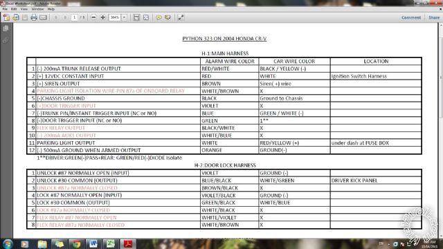
Here is my problem. I just bought a Python 3203P (model 323) and about to install it myself. I've got wire guide for my 2004 Honda CR-V (thanks to https://www.the12volt.com, but the wire guide I got with alarm is a bit confusing to say at least. Eventually I was able to figure most of wiring out, but diagram doesn't show or explain where I suppose to connect 2 accessory wires from Honda. It shows none! And also what are those "Flex Relays"? How can I use it? Called Directech-no help, they said Pythons intended for only professional installation so they are restricted to give me information on installation! Total BS!!! python 323, avital 4003, pkh34 -- posted image.
Here is what I was able to figure out. If anyone could check if I got it right I would really appreciate! python 323, avital 4003, pkh34 -- posted image.
python 323, avital 4003, pkh34 -- posted image.
PS couldn't upload PDF, sorry
superden 
Member - Posts: 17
Member spacespace
Joined: October 13, 2011
Location: New Jersey, United States
Posted: October 14, 2011 at 4:01 AM / IP Logged  
Sorry for quality, but that is the best I could come up with...
python 323, avital 4003, pkh34 -- posted image.
Should I just post plain text?
superden 
Member - Posts: 17
Member spacespace
Joined: October 13, 2011
Location: New Jersey, United States
Posted: October 14, 2011 at 4:22 AM / IP Logged  
This one is probably easier to read, sorry for all confusion with my post - 1st timer python 323, avital 4003, pkh34 -- posted image.
PYTHON 323 ON 2004 HONDA CR-V                    
                    
H-1:MAIN HARNESS                    
                 ALARM WIRE COLOR / CAR WIRE COLOR      
1     (-) 200mA TRUNK RELEASE OUTPUT     RED / WHITE      BLACK / YELLOW (-)     
2     (+) 12VDC CONSTANT INPUT      RED               WHITE     
3     (+) SIREN OUTPUT             BROWN               Siren( +) wire     
4         PARKING LIGHT ISOLATION
      WIRE-PIN 87a OF ONBOARD RELAY     WHITE/ BROWN      X     
5     (-)CHASSIS GROUND              BLACK               Ground to Chassis     
6     (+)DOOR TRIGGER INPUT             VIOLET         X     
7     (-)TRUNK PIN/INSTANT TRIGGER
     INPUT (NC or NO)      BLUE               GREEN / WHITE (-)     
8     (-)DOOR TRIGGER     DR.:GREEN(-)DIODE Isolate
     INPUT (NC or NO)     GREEN               PAS.&REAR:GREEN/ RED(-)     
9     FLEX RELAY OUTPUT             BLACK/ WHITE      X     
10     (-) 200mA AUX1 OUTPUT             WHITE/ BLUE      X     
11     PARKING LIGHT OUTPUT             WHITE               RED / YELLOW (+)      
12     (-) 500mA GROUND WHEN
    ARMED OUTPUT      ORANGE               GROUND(-)     
                    
H-2:DOOR LOCK HARNESS                    
1     UNLOCK #87 NORMALLY OPEN(INPUT) VIOLET               GROUND (-)     
2     UNLOCK #30 COMMON (OUTPUT)      BLUE/BLACK      WHITE/ GREEN      
3     UNLOCK #87a NORMALLY CLOSED     BROWN / BLACK      X     
4     LOCK #87 NORMALLY OPEN (INPUT)     VIOLET/BLACK      GROUND (-)     
5     LOCK #30 COMMON (OUTPUT)     GREEN/ BLACK      WHITE/ BLUE     
6     LOCK #87a NORMALLY CLOSED     WHITE/ BLACK      X     
7     FLEX RELAY #87 NORMALLY OPEN     WHITE/ VIOLET      X     
8     FLEX RELAY #87a NORMALLY CLOSED     WHITE/ BROWN      X     
                    
H-3: AUXILARY HARNESS                    
1     (-)200mA AUX 4 OUTPUT             ORANGE / BLACK      X     
2     (-)200mA AUX 3 OUTPUT             WHITE/ BLACK      X     
3     (-)200mA AUX 2 OUTPUT             WILET/BLACK      X     
4     (-)200mA FACTORY ALARM
             DISARM OUTPUTLIGHT        GREEN/ BLACK      X     
5     (+) IGNITION INPUT             YELLOW          BLACK / YELLOW     
6     (-)200mA HORN HONK OUTPUT     BROWN               ORANGE     
7     N/O or N/C (-) HOOD PIN SWITCH     GREY               X     
                    
STARTER KILL HARNESS                     
"BLACK / WHITE wire, located under dash at FUSE / RELAY BOX Starter "                    
Wire Must Be Accessed After Fuse Block To Prevent Check Engine Light.
Cut BLACK/ WHITE wire & connect as directed.                    
1     STARTER-COMMON (KEY SIDE)          GREEN / WHITE   KEY SIDE BLACK/ WHITE     
2     STARTER-NORMALLY OPEN(MOTOR SIDE)    GREEN         MOTOR SIDE BLACK/ WHITE      
3     STARTER-NORMALLY CLOSED(MOTOR SIDE) GREEN/ BLACK   X     


superden 
Member - Posts: 17
Member spacespace
Joined: October 13, 2011
Location: New Jersey, United States
Posted: October 14, 2011 at 4:27 AM / IP Logged  
Sorry, it looked better before posting... I guess it was formatted python 323, avital 4003, pkh34 -- posted image.
superden 
Member - Posts: 17
Member spacespace
Joined: October 13, 2011
Location: New Jersey, United States
Posted: October 14, 2011 at 4:36 AM / IP Logged  
python 323, avital 4003, pkh34 -- posted image.
Here is my pdf: http://www.slideshare.net/superden001/excel-worksheet-9691324
howie ll 
Pot Metal - Posts: 16,466
Pot Metal spacespace
Joined: January 09, 2007
Location: United Kingdom
Posted: October 14, 2011 at 4:49 AM / IP Logged  
Is this an alarm or an R/Start. If you're using it as an alarm the ACC x 2 aren't relevant.
Also on the starter kill harness use 3 instead of 2 it's safer.
Everything else looks OK except the orange GWA. That should NOT be grounded, it's used for triggering accessories such as window closers.
superden 
Member - Posts: 17
Member spacespace
Joined: October 13, 2011
Location: New Jersey, United States
Posted: October 14, 2011 at 1:28 PM / IP Logged  
howie ll - Appreciate your help!
Yes, I'm trying to install remote start feature also, bypass module on it's way. Could it be that they moved ACCx2 wires to bypass module harness?
As to Orange GWA-I was told it is used by starter kill...
Where do I connect 3rd wire from starter kill harness?
Thanks
howie ll 
Pot Metal - Posts: 16,466
Pot Metal spacespace
Joined: January 09, 2007
Location: United Kingdom
Posted: October 14, 2011 at 1:37 PM / IP Logged  
No it isn't. Used for accessories such as window closers. You only need to use 1 and 3 of the starter kill.
You will eventually use the flex relay for ACC 2.
superden 
Member - Posts: 17
Member spacespace
Joined: October 13, 2011
Location: New Jersey, United States
Posted: October 14, 2011 at 1:48 PM / IP Logged  
Also no Tach wire on RS/Alarm harness! Doesn't need it?
Is that some kind of new generation alarm? So much confusion with wires...
superden 
Member - Posts: 17
Member spacespace
Joined: October 13, 2011
Location: New Jersey, United States
Posted: October 14, 2011 at 1:54 PM / IP Logged  
You will eventually use the flex relay for ACC 2 - That's what I thought!
But which one ACC1 or ACC2? if both then how?
Man, you are the best! python 323, avital 4003, pkh34 -- posted image. No one ever helped me on other forums
Thank you
Page of 3

  Printable version Printable version Post ReplyPost New Topic
You cannot post new topics in this forum
You cannot reply to topics in this forum
You cannot delete your posts in this forum
You cannot edit your posts in this forum
You cannot create polls in this forum
You cannot vote in polls in this forum

  •  
Search the12volt.com
Follow the12volt.com Follow the12volt.com on Facebook
Tuesday, May 13, 2025 • Copyright © 1999-2025 the12volt.com, All Rights Reserved Privacy Policy & Use of Cookies
Disclaimer: *All information on this site ( the12volt.com ) is provided "as is" without any warranty of any kind, either expressed or implied, including but not limited to fitness for a particular use. Any user assumes the entire risk as to the accuracy and use of this information. Please verify all wire colors and diagrams before applying any information.

Secured by Sectigo
the12volt.com spacer
Support the12volt.com
Top
the12volt.com spacer