


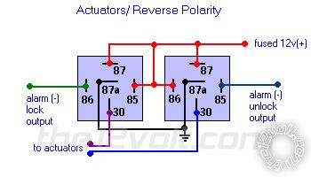
 You could then wire your lock output from the 211HV to both pairs of relays. Then the unlock would wire to the drivers pair of relays and the 2nd unlock wire would go to the passenger side pair of relays.
Essentially you would no longer be using the 211HV internal relays to operate the actuators. You would be using external relay pairs for each side. The reason being that the lock output needed from the 211HV to control the passenger side relay pair is internal and I cant think of any way to get a locking output for the 2nd actuator.
Maybe there is a way to do it keeping the current setup but I am not able to think of it. Hopefully someone else may be able to chime in if they can figure out how to do it.
Personally I would just keep them the way they are due to the added work involved, but that is up to you.
Good luck.
You could then wire your lock output from the 211HV to both pairs of relays. Then the unlock would wire to the drivers pair of relays and the 2nd unlock wire would go to the passenger side pair of relays.
Essentially you would no longer be using the 211HV internal relays to operate the actuators. You would be using external relay pairs for each side. The reason being that the lock output needed from the 211HV to control the passenger side relay pair is internal and I cant think of any way to get a locking output for the 2nd actuator.
Maybe there is a way to do it keeping the current setup but I am not able to think of it. Hopefully someone else may be able to chime in if they can figure out how to do it.
Personally I would just keep them the way they are due to the added work involved, but that is up to you.
Good luck. Printable version


| You cannot post new topics in this forum You cannot reply to topics in this forum You cannot delete your posts in this forum You cannot edit your posts in this forum You cannot create polls in this forum You cannot vote in polls in this forum |

| Search the12volt.com |
Follow the12volt.com 
Friday, May 15, 2026 • Copyright © 1999-2026 the12volt.com, All Rights Reserved • Privacy Policy & Use of Cookies

Friday, May 15, 2026 • Copyright © 1999-2026 the12volt.com, All Rights Reserved • Privacy Policy & Use of Cookies
Disclaimer:
*All information on this site ( the12volt.com ) is provided "as is" without any warranty of any kind, either expressed or implied, including but not limited to fitness for a particular use. Any user assumes the entire risk as to the accuracy and use of this information. Please
verify all wire colors and diagrams before applying any information.
