The Ready Remote 24921 is an older and very basic remote start. There are very few features that you can configure on this unit, and limited functionality. It would be easier, cleaner, and allow for more support if needed, to use an upgraded brand of Alarm/Remote start combination in this type of application. You will also get increased remote range from a newer system (I believe the Ready remote 24921 was only around 500 ft, Hornet 700T has an internal antenna, so that distance is limited as well). Audiovox, Compustar, and Directed's Viper/Python/Avital all have versions that will improve on what you have and provide more range.
That being said, you can add the Ready Remote 24921 to your car. Keep in mind that limitations come with the basic unit and the combinations you are trying to put together.
As far as the alarm combination, the Hornet 700T monitors the ignition wire in the car. This will need to be opened during remote start, which will keep your alarm from going off due to the ignition activating. This can be done with your unit, however it will require 2 diodes and a relay.
The diodes can be general purpose, such as 1N4001. The relay would be 5 pin general purpose automotive relay (refer to the relay section of this site). You would connect the bands of both diodes together and also to the H1/1 Blue wire of the 24921. The other (non-banded) ends of the diodes create 2 separate Ground When Running connections; one to connect to the 555UW Ground when Running input, and the other will go to the relay to work around the alarm's ignition connection during remote start. The relay connections will be:
86: +12V
85: the unbanded Ground when Running signal described above
Cut the Hornet's Yellow H1/9 Alarm ignition wire.
Relay Pin 30: one side of the cut Hornet ignition wire
Relay Pin 87A: Other side of the cut Hornet ignition wire
Relay Pin 87: Not connected
Do you want to control the Remote Start from the Hornet Alarm? If so, you would use the Red/White Channel 2 output from the Hornet alarm to connect to the
H1/6 - White/Blue (Remote Start Activation Input). I believe that the older 24921 requires 2 pulses to activate, so you would activate the channel 2 output 2 times to activate the remote start. Even if this Activation input is hooked up, the Ready Remote 24921 remotes will still remain active and can be used to enable the remote start if desired.
The Ready Remote 24921 only has a negative parking light output. So for H1/8 White output from the Ready Remote unit, using the PARKING LIGHTS ( - )BLUE (-)@ HEADLIGHT SWITCH UNDER STEERING COLUMN COVER will be simpler, as it won't require an additional relay.
H1/7 - LT. Green/Black (Factory Alarm Disarm) is used to disable a factory alarm (Which you do not have), so you would not use this.
Be careful in connecting to colors in your Honda without verifying. Get access to a DC voltmeter and test each wire before hooking up to it.
Primary Harness H1 8-pin connector Honda 2005 LX
H1/1 - Blue ............................................Ground When Running (To the banded end of 2 diodes; one unbanded end to the 556uw Immobilizer Bypass, the other unbanded end to a relay, see above)
H1/2- violet/white ...........................................Tach:Blue(AC) @ TACH TEST CONNECTOR (2 PIN CONNECTOR ON THE PASSENGER SIDE OF THE BATTERY).
H1/3 - Brown ............................................Brake (+): White/Black @ SWITCH ABOVE BRAKE PEDAL
H1/4 - Gray ............................................HoodPin
H1/5 - Black ..........................................Ground
H1/6 - White/Blue (Remote Start Activation Input)...............Activation Input: To Hornet Red/White Ch 2 output
H1/7 - LT. Green/Black (Factory Alarm Disarm/RAP Cancellation)..Not Used
H1/8 - White ............................................Headlights(-):Blue(-) @ HEADLIGHT SWITCH UNDER STEERING COLUMN COVER
Relay Wires 6-connectors
A - Violet............................................... Starter: Black/White @ IGNITION SWITCH HARNESS
B - Red.................................................. 12V: White @ IGNITION SWITCH HARNESS
C-Orange................................................. Accy 1:Black/Red @ IGNITION SWITCH HARNESS
D-Pink................................................... Ign1:Black/Yellow @ IGNITION SWITCH HARNESS
E-Red.................................................... 12V:White @ IGNITION SWITCH HARNESS
F- Pink/White............................................ N/A (IGN2)
Lectric Guy


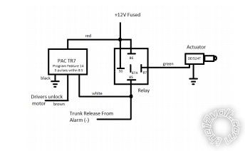 Your trunk solenoid would take the place of the actuator in the diagram. If you don't end up using the Hornet Red/White to activate the remote start, you could also hook up the alarm's Red/White output to the relay pin 85 along with the TR-7's output if you want, no issues. Then either the factory remotes or the alarm's remotes would pop the trunk. Of course, just make sure that the alarm is not armed if you use the factory remote.
For TR-7 Programming, you would use Feature #14, Set it up to could 3 (unlock) pulses in 8 seconds. There is a switch to place the TR-7 in program mode, and back to operational mode when you are done.
Programming the TR-7 can be frustrating, I recommend using a push button switch to program it on the bench before installing. If you make a mistake, just power off and on and restart the programming.
Be patient and follow the PAC guide and you should be OK.
Your trunk solenoid would take the place of the actuator in the diagram. If you don't end up using the Hornet Red/White to activate the remote start, you could also hook up the alarm's Red/White output to the relay pin 85 along with the TR-7's output if you want, no issues. Then either the factory remotes or the alarm's remotes would pop the trunk. Of course, just make sure that the alarm is not armed if you use the factory remote.
For TR-7 Programming, you would use Feature #14, Set it up to could 3 (unlock) pulses in 8 seconds. There is a switch to place the TR-7 in program mode, and back to operational mode when you are done.
Programming the TR-7 can be frustrating, I recommend using a push button switch to program it on the bench before installing. If you make a mistake, just power off and on and restart the programming.
Be patient and follow the PAC guide and you should be OK.
 Printable version


