the12volt.com spacer
icon

relay diagram for alarm


Post ReplyPost New Topic
< Prev Topic Next Topic >
jgw01 
Member - Posts: 13
Member spacespace
Joined: June 03, 2011
Location: United Kingdom
Posted: June 03, 2011 at 2:06 PM / IP Logged  

Hello,

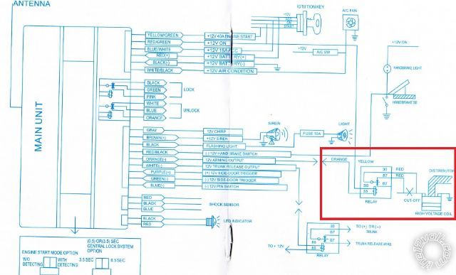
I am installing a car alarm and  i'm having trouble understanding the relay for starter kill, here is the wiring diagram.

relay diagram for alarm -- posted image.

Its the relay in the red box. The numbers look nothing like the relay supllied. The supplied relay is 5 pin 30,85,86,87,87a. Can anyone make sense of what it is asking me to do? I have very basic knowledge of relays.

Thank you

jgw01 
Member - Posts: 13
Member spacespace
Joined: June 03, 2011
Location: United Kingdom
Posted: June 03, 2011 at 2:10 PM / IP Logged  

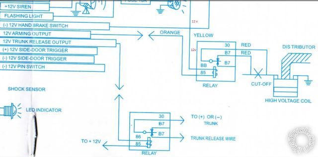
relay diagram for alarm -- posted image.

sorry hope this is clearer

KPierson 
Platinum - Posts: 3,527
Platinum spaceThis member consistently provides reliable informationspace
Joined: April 14, 2005
Location: Ohio, United States
Posted: June 03, 2011 at 2:35 PM / IP Logged  
Thats not a starter kill - that is an ignition kill. Same principal, but they are showing you cutting power to the coil, thus preventing ignition.
The more acceptable approach is to interrupt the starter wire coming from the keyswitch to the starter solenoid.
Make sure you connect the + side of the relay to switched ignition NOT constant 12vdc.
Kevin Pierson
jgw01 
Member - Posts: 13
Member spacespace
Joined: June 03, 2011
Location: United Kingdom
Posted: June 03, 2011 at 3:04 PM / IP Logged  

Thank you for your reply, sorry but my relay knowledge is limited what numbers do I connect each wire to.

Thank you

jgw01 
Member - Posts: 13
Member spacespace
Joined: June 03, 2011
Location: United Kingdom
Posted: June 03, 2011 at 4:39 PM / IP Logged  

so would the starter go to 30 and 87a with arming out to 85. Is that it or relay need ground too?

Thanks

KPierson 
Platinum - Posts: 3,527
Platinum spaceThis member consistently provides reliable informationspace
Joined: April 14, 2005
Location: Ohio, United States
Posted: June 03, 2011 at 4:42 PM / IP Logged  
Yes, your pin numbers are correct. I would assume the "arming output" is the ground, connect it to 85. 86 will connect to switched ignition. 30 and 87A will be your starter wires.
Kevin Pierson
howie ll 
Pot Metal - Posts: 16,466
Pot Metal spacespace
Joined: January 09, 2007
Location: United Kingdom
Posted: June 03, 2011 at 5:06 PM / IP Logged  
One look at that diagram says bin it, it's a POS.
It's also telling you to cut the ignition which is a real no-no.
It should be the starter, this is the correct diagram relay_starter_cut.bmp
howie ll 
Pot Metal - Posts: 16,466
Pot Metal spacespace
Joined: January 09, 2007
Location: United Kingdom
Posted: June 03, 2011 at 5:08 PM / IP Logged  
Sorry Kevin, didn't see your post, that unit's a Fleabay Chinese piece of junk. Can you even see how it gets it's tach sense? Please don't say oil pressure switch.
jgw01 
Member - Posts: 13
Member spacespace
Joined: June 03, 2011
Location: United Kingdom
Posted: June 03, 2011 at 5:38 PM / IP Logged  

Thank you very much for your help, i now have the confidence to go ahead.

It has no tach sense or anything else to compensate. The remote start will not used anyway. It has no use whatsoever in the south east of England where the temperature is rarely below freezing or above 80oc.

Thanks again.

jgw01 
Member - Posts: 13
Member spacespace
Joined: June 03, 2011
Location: United Kingdom
Posted: June 03, 2011 at 5:41 PM / IP Logged  
Also I would never have used the ignition wire. If the relay had failed while driving my car would've been a mess.
Page of 3

  Printable version Printable version Post ReplyPost New Topic
You cannot post new topics in this forum
You cannot reply to topics in this forum
You cannot delete your posts in this forum
You cannot edit your posts in this forum
You cannot create polls in this forum
You cannot vote in polls in this forum

  •  
Search the12volt.com
Follow the12volt.com Follow the12volt.com on Facebook
Monday, May 5, 2025 • Copyright © 1999-2025 the12volt.com, All Rights Reserved Privacy Policy & Use of Cookies
Disclaimer: *All information on this site ( the12volt.com ) is provided "as is" without any warranty of any kind, either expressed or implied, including but not limited to fitness for a particular use. Any user assumes the entire risk as to the accuracy and use of this information. Please verify all wire colors and diagrams before applying any information.

Secured by Sectigo
the12volt.com spacer
Support the12volt.com
Top
the12volt.com spacer