the12volt.com spacer
icon

pac ms frd1 and 4 channel amp


Post ReplyPost New Topic
< Prev Topic Next Topic >
i am an idiot 
Platinum - Posts: 13,667
Platinum spaceThis member consistently provides reliable informationspace
Joined: September 21, 2006
Location: Louisiana, United States
Posted: August 06, 2011 at 9:35 PM / IP Logged  

Pac-Audio.com has been in business since before 1985.  That is when I first learned of this company.  They made line out converters.  This was so long ago that the model number was SNI-8.  That is a line out converter for an 8 watt per channel radio.   Shortly after that time, high power radios became more and more frequent.  They had to add the SNI-15 to their lineup.  That is for a 15 watt per channel radio.  Point being, they know people install amplifiers into their vehicles. 

In January this year we installed a Double Din DVD player into a 2011 F-150 with the Sync system.  This piece worked flawlessly.   Customer came in yesterday wanting to install a 4 channel amp and upgrade his door speakers.  The installer is giving me trouble telling me that the module is not going to work with an amplifier.  My argument was, dude, they have been making LOCs for over 25 years, they know people are putting amps in their cars. The module will handle the power of an amp.  Guess who the idiot was.  Yup it was me.  We did get it in and working.  Took some work, but we made it happen.  Pac tech support was freaking out when I told them we ran an amp on the unit, 

All was fine at low to medium volume.  Problem was at high volume with all 4 channels driven, the module would power the radio down.  That is how it kills rear speakers to answer a bluetooth call.  2 channels at a time would work much better, amp had to reach clipping before unit would shut down.  Thought this was going to be an easy fix, bypass the box with the rear speakers.  Front has to run through it in order for the bluetooth to work.  That did not help much.  My customers Love them some clipping.  It was still shutting down.

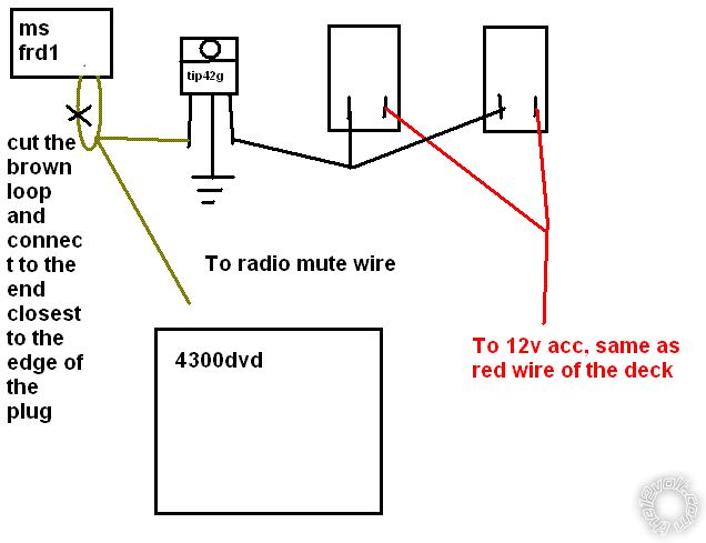
Pac tech support did tell me about the brown loop.  If you cut that loop, and connect the radio's mute wire to the brown loop wire that is closest to the end of the plug, this will mute the radio instead of killing power.  It would mute the radio when the volume was turned up, this was much better than having the deck power down and have to wait for it to come back up. 

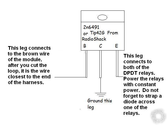
What was done to fix the problem:  I had to use a transistor and 2 DPDT relays from Radio Shack to completely bypass the module with all amp wiring.  I will post diagram for the transistor.  Transistor is triggered by the brown wire of the pac module.  Same wire that mutes the deck.

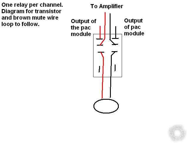
Relays wired as follows:  Common terminals to speaker wires.  Only front channels need to go through relays.  Rear channels can not go through the module, just wire the rear speakers directly to the amplifier.

Normally closed contacts to the output of the amplifier.

Normally open contacts to the output of the module.  This is only needed for bluetooth phone operation.

So don't go thinking that Pac knows you are going to amplify your systen, and make their interface modules accordingly.  If you think that you may look like you have no clue.  Like me.

i am an idiot 
Platinum - Posts: 13,667
Platinum spaceThis member consistently provides reliable informationspace
Joined: September 21, 2006
Location: Louisiana, United States
Posted: August 06, 2011 at 9:46 PM / IP Logged  
pac ms frd1 and 4 channel amp -- posted image.
i am an idiot 
Platinum - Posts: 13,667
Platinum spaceThis member consistently provides reliable informationspace
Joined: September 21, 2006
Location: Louisiana, United States
Posted: September 29, 2011 at 3:39 PM / IP Logged  

If using Bosch/Now Tyco relays.  30 is the common terminal.  this connection goes to the speakers.  87A is the normally closed connection, this is to be connected to the aftermarket amplifier.  87 is the normally open connection, this connects to the output wires of the above mentioned Pac integration harness.

If using these relays, it will take a total of 4 relays.  2 for the left speaker and 2 for the right speaker.  One relay for the positive wire, and one for the negative wire. 

If you do use a DPDT relay, post a picture of the connetions of that relay and I can give more guidance.

rocketpod23 
Member - Posts: 7
Member spacespace
Joined: September 29, 2011
Location: Georgia, United States
Posted: September 30, 2011 at 4:03 AM / IP Logged  
Currently trying this with a 2010 f150. I have a Pioneer AVH P4300 HU, with the PAC MSFRD1 Sync adapter, and will be trying to run a Rockford Fosgate 4 channel amplifier to my Pioneer 3 way door speakers.
I've searched the net, and talked to a lot of tech support, in an attempt to make this work without sacrificing any of my vehicle's Sync capabilities. If this works, I will definitely give feedback. I know I can't be the only one looking to do this. It may time a couple of weeks to get all this together, but I will certainly post results.
i am an idiot 
Platinum - Posts: 13,667
Platinum spaceThis member consistently provides reliable informationspace
Joined: September 21, 2006
Location: Louisiana, United States
Posted: September 30, 2011 at 10:57 AM / IP Logged  
It does work just as you desire. It has been in the truck since a week before I initially posted. Same exact head unit in a 2011 truck.
Transistor part number is 276-2027
Relay part number is 275-216 you will need 2 of these. Relays 10 bucks each, transistor less than 2 dollars. You will need some solder and a soldering iron if you do not already have one. If you have to purchase an iron, do not waste your money on a Radio Shack iron. Spend a few extra dollars and get a Weller iron.
i am an idiot 
Platinum - Posts: 13,667
Platinum spaceThis member consistently provides reliable informationspace
Joined: September 21, 2006
Location: Louisiana, United States
Posted: October 01, 2011 at 11:03 PM / IP Logged  
\If you have not went to Radio Shack yet, pick up a diode while there.  276-1101  or 276-1102  or 1103
i am an idiot 
Platinum - Posts: 13,667
Platinum spaceThis member consistently provides reliable informationspace
Joined: September 21, 2006
Location: Louisiana, United States
Posted: October 02, 2011 at 6:31 PM / IP Logged  

pac ms frd1 and 4 channel amp -- posted image.

I did not get a layout of the relay from Radio Shack.  They did have a picture, from what I could see through the smoked plexiglass cover, this should be accurate.  Check against this info before wiring it up.  Top set of contacts should be the NC (Normally Closed) contacts.  Just below that is the NO contacts.  Then the Common contacts.  Coil connections are at the bottom of the relay.

i am an idiot 
Platinum - Posts: 13,667
Platinum spaceThis member consistently provides reliable informationspace
Joined: September 21, 2006
Location: Louisiana, United States
Posted: October 02, 2011 at 7:09 PM / IP Logged  

I forgot to draw the diode on the diagram.  It needs to go across the coil of one of the relays.  The end of the diode that has the band on it MUST be connected to the terminal that has positive voltage.  The transistor does not need a heat sink.  The tab of the transistor is connected to the middle leg.  There is ground on the tab.  If you want to mount it to a bracket or directly to the chassis, that will be fine. 

pac ms frd1 and 4 channel amp -- posted image.

i am an idiot 
Platinum - Posts: 13,667
Platinum spaceThis member consistently provides reliable informationspace
Joined: September 21, 2006
Location: Louisiana, United States
Posted: October 03, 2011 at 8:33 PM / IP Logged  

I looked at the pictures you sent.  The above diagrams are exactly what you need. 

Did you buy the exact part number relay I suggested?  They sell a 3 amp and a 10 amp device.   The pic looks like it may be smaller in size than the ones I have used.  if it is the 3 amp unit, I have no idea how long it will last.

rocketpod23 
Member - Posts: 7
Member spacespace
Joined: September 29, 2011
Location: Georgia, United States
Posted: October 04, 2011 at 10:40 AM / IP Logged  
grr, the relays I got are Part Number- 275-0218. I picked them up before your post listing the specific PN. I wander if they are the same. Judging from the new diagrams you posted, and the diagram on the package of the relay, they seem to be the same.
Page of 3

  Printable version Printable version Post ReplyPost New Topic
You cannot post new topics in this forum
You cannot reply to topics in this forum
You cannot delete your posts in this forum
You cannot edit your posts in this forum
You cannot create polls in this forum
You cannot vote in polls in this forum

  •  
Search the12volt.com
Follow the12volt.com Follow the12volt.com on Facebook
Sunday, April 28, 2024 • Copyright © 1999-2024 the12volt.com, All Rights Reserved Privacy Policy & Use of Cookies
Disclaimer: *All information on this site ( the12volt.com ) is provided "as is" without any warranty of any kind, either expressed or implied, including but not limited to fitness for a particular use. Any user assumes the entire risk as to the accuracy and use of this information. Please verify all wire colors and diagrams before applying any information.

Secured by Sectigo
the12volt.com spacer
Support the12volt.com
Top
the12volt.com spacer