the12volt.com spacer
icon

diode to door trigger


Post ReplyPost New Topic
< Prev Topic Next Topic >
chadstrawn 
Member - Posts: 10
Member spacespace
Joined: November 01, 2008
Location: Ontario, Canada
Posted: November 01, 2008 at 5:00 PM / IP Logged  
ok, so i work on police cars  installing things for a to z. recently doing an alarm i did some research and found out you have to put a diode going to the door input trigger( -) , stripe away so like this...
-------|<------- to trigger input on alarm(negative input)
why is it that the diode has to face this way and not ----------->|-----------
is it because the trigger input wire is more possitive then the negative signal from the door triggers
i am puzzled
thanks for any help
i am an idiot 
Platinum - Posts: 13,667
Platinum spaceThis member consistently provides reliable informationspace
Joined: September 21, 2006
Location: Louisiana, United States
Posted: November 01, 2008 at 5:14 PM / IP Logged  
chadstrawn 
Member - Posts: 10
Member spacespace
Joined: November 01, 2008
Location: Ontario, Canada
Posted: November 01, 2008 at 6:38 PM / IP Logged  
i found that link but is what i thot right? alarm side is more positive so thats why the diodes are reversed like that? if i am wrong , i am looking for an answer, ty
reax222 
Copper - Posts: 220
Copper spacespace
Joined: March 11, 2006
Location: United States
Posted: November 01, 2008 at 6:44 PM / IP Logged  
I get confused on diodes too, it helps to only think of it flowing positive. Positive flows from the anode to the cathode (strip side), The door trigger sees a negative, so positive has to flow from the alarm to the door wire. When the door is opened the power goes from the alarm to ground making the wire a ground.
Am I close?
i am an idiot 
Platinum - Posts: 13,667
Platinum spaceThis member consistently provides reliable informationspace
Joined: September 21, 2006
Location: Louisiana, United States
Posted: November 01, 2008 at 6:58 PM / IP Logged  
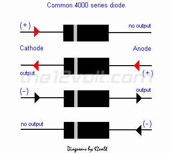
What kind of vehicle?    Does the vehicle have 4 seperate door open indicators on the dash of the vehicle?   If so the reason for the diode isolation is to keep the door open indicators working properly.  The diode is a directional device, if it is installed backwards the signal from the pinswitch will not reach the alarm.  The link I posted earlier has the 4 pictures of the diodes that show which way a particular voltage will or will not flow through the diode. 
chadstrawn 
Member - Posts: 10
Member spacespace
Joined: November 01, 2008
Location: Ontario, Canada
Posted: November 01, 2008 at 7:18 PM / IP Logged  
what i am trying to say is the alarm has a negative door trigger input, and i have to put a diode on each door trigger in the BCM of an impala, but i understand that a diode flows positive to neg, anode to cathode, but i am confused on how when u need to send a negative output to the alarm u have to have the diode looking like this
this end is negative trigger from BCM when door opens---------|<-----------this is the door trigger input to the alarm
      so this means, if u are sending a ground signal to the alarm, u have to have the diode opposite to what u would normally put it( --------->|-------- )
its just so confusing trying to learn new things
chadstrawn 
Member - Posts: 10
Member spacespace
Joined: November 01, 2008
Location: Ontario, Canada
Posted: November 01, 2008 at 7:20 PM / IP Logged  
reax222 wrote:
I get confused on diodes too, it helps to only think of it flowing positive. Positive flows from the anode to the cathode (strip side), The door trigger sees a negative, so positive has to flow from the alarm to the door wire. When the door is opened the power goes from the alarm to ground making the wire a ground.
Am I close?
this kinda makes sense but doesnt at the same time lol :P
i am an idiot 
Platinum - Posts: 13,667
Platinum spaceThis member consistently provides reliable informationspace
Joined: September 21, 2006
Location: Louisiana, United States
Posted: November 01, 2008 at 7:24 PM / IP Logged  

Third picture down shows which way negative voltage travels through the diode.    When you put the diode in the other direction, you must have positive voltage traveling through it.  Positive voltage flows in the opposite direction.  The ( - ) indicates negative voltage applied to that point.   The output/no output on the other end indicates whether or not the voltage goes through the diode.

diode to door trigger -- posted image.

chadstrawn 
Member - Posts: 10
Member spacespace
Joined: November 01, 2008
Location: Ontario, Canada
Posted: November 01, 2008 at 7:41 PM / IP Logged  
i am an idiot wrote:

Third picture down shows which way negative voltage travels through the diode.    When you put the diode in the other direction, you must have positive voltage traveling through it.  Positive voltage flows in the opposite direction.

diode to door trigger -- posted image.

ty i seen this but i was hoping i could get an answer telling me why this works this way, doesnt make sense to me lol
maybe i have been told by u guys, i must not be reading what u guys are writing right lol
i am an idiot 
Platinum - Posts: 13,667
Platinum spaceThis member consistently provides reliable informationspace
Joined: September 21, 2006
Location: Louisiana, United States
Posted: November 01, 2008 at 7:46 PM / IP Logged  

I added a line to my last post after you read it.  It may help explain the pictures.

http://en.wikipedia.org/wiki/Diode

Page of 2

  Printable version Printable version Post ReplyPost New Topic
You cannot post new topics in this forum
You cannot reply to topics in this forum
You cannot delete your posts in this forum
You cannot edit your posts in this forum
You cannot create polls in this forum
You cannot vote in polls in this forum

  •  
Search the12volt.com
Follow the12volt.com Follow the12volt.com on Facebook
Sunday, April 28, 2024 • Copyright © 1999-2024 the12volt.com, All Rights Reserved Privacy Policy & Use of Cookies
Disclaimer: *All information on this site ( the12volt.com ) is provided "as is" without any warranty of any kind, either expressed or implied, including but not limited to fitness for a particular use. Any user assumes the entire risk as to the accuracy and use of this information. Please verify all wire colors and diagrams before applying any information.

Secured by Sectigo
the12volt.com spacer
Support the12volt.com
Top
the12volt.com spacer