the12volt.com spacer
icon

2007 gmc acadia remote start


Post ReplyPost New Topic
< Prev Topic Next Topic >
maxxrpm 
Member - Posts: 16
Member spacespace
Joined: September 19, 2010
Location: Alberta, Canada
Posted: September 19, 2010 at 12:32 PM / IP Logged  

Hi guys, I have a HIH cx2300 series remote start.  I tried installing it on my 2007 acaida yesterday.  I am having some issues with the wiring and connecting it to the bypass module PKUCG2X.  The RS attemps to start by i get an error on the dash "Service Theft Deterrent System"  I tried moving ot another wire on the dash thinking i may be on the wrong data wire but still the same.  The bypass module tells me to connect a wire to (-) to ground when running output.  Not sure which wire this is on the RS unit.  Is there a way i can test for this wire.  Also is it really important or necessary to install the resistors on the starter and accessory wire.  Also do i need to connect the Factory Alarm Disarm wire.  Thanks.

Jamie Squire
kreg357 
Platinum - Posts: 7,787
Platinum spaceThis member has made a donation to the12volt.com. Click here for more info.spaceThis member has been recognized as an authority in Electrical Theory. Click here for more info.spaceThis member has been recognized as an authority in Mobile Security and Convenience. Click here for more info.spacespace
Joined: January 30, 2009
Location: Pennsylvania, United States
Posted: September 19, 2010 at 8:50 PM / IP Logged  

I am unable to find the install guide for your CX2300 remote start.  However, there should be an output wire with a label / name like GWR, Ground When Running, (-) Status Output, (-) 2nd Status, (-) Ignition3 Output, Negative Out when running, etc    This wire should show a ground when the remote start goes active ( a second or two before the Ignition wire goes to +12 volts ).  This wire is connected to the bypass Brown GWR Status wire.

Follow the PKU CG2X install guide for Install Type D pages 7 and 8.  You will need the relay and resistors specified.   ( See the note on Page 7 about the Resistor Code wire for testing with a Digital Multi Meter and computer codes )   The Data wire should be White.  If the CX2300 does not supply 2 Accessory outputs, you will need more relays for the ACC2 connection.

See Section C on Page 8 for bypass programming.

Soldering is fun!
maxxrpm 
Member - Posts: 16
Member spacespace
Joined: September 19, 2010
Location: Alberta, Canada
Posted: September 20, 2010 at 8:39 AM / IP Logged  
Hi.. THANKS.  I have a 2nd ign wire but know 2nd Acc wire.  How do i go about hooking this wire in and to which one does it connect to the Vehicle.  Again THANKS
Jamie Squire
maxxrpm 
Member - Posts: 16
Member spacespace
Joined: September 19, 2010
Location: Alberta, Canada
Posted: September 20, 2010 at 8:48 AM / IP Logged  
Also with this bypass module it says to loop at least 3 or 5 loops and do not put on metal surface.  Well this thing comes with a loop about 2"  and the ign is about 1.5" diameter so it makes it impossible to put 3 or 5 loops and the ignition is metal.  What do i do here, do i just put the loop wire over the outer ring of the ignition and take up the slack with a tie wrap or something? 
Jamie Squire
kreg357 
Platinum - Posts: 7,787
Platinum spaceThis member has made a donation to the12volt.com. Click here for more info.spaceThis member has been recognized as an authority in Electrical Theory. Click here for more info.spaceThis member has been recognized as an authority in Mobile Security and Convenience. Click here for more info.spacespace
Joined: January 30, 2009
Location: Pennsylvania, United States
Posted: September 20, 2010 at 11:41 AM / IP Logged  

For the extra Accessory circuit, use this Install guide as a reference:  http://www.readyremote.com/pdf/manuals/24921.pdf   On page 18 there is a nice diagram of the wiring for the extra relays needed to provide the extra accessory output.  You will need two 30/40A SPDT relays, two fuse holders & fuses, etc.

The antenna loop should be a long black wire, about 24 inches.  It gets wrapped around the ingition cylinder in the location shown.  The "don't put on metal surface" applies to the PKUCG2X module itself.

Soldering is fun!
maxxrpm 
Member - Posts: 16
Member spacespace
Joined: September 19, 2010
Location: Alberta, Canada
Posted: September 20, 2010 at 1:25 PM / IP Logged  
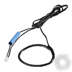
Yes the wire is 24" long but the loop om the end makes it impossible to wrap 3 or 5 times.
2007 gmc acadia remote start -- posted image.
kreg357 
Platinum - Posts: 7,787
Platinum spaceThis member has made a donation to the12volt.com. Click here for more info.spaceThis member has been recognized as an authority in Electrical Theory. Click here for more info.spaceThis member has been recognized as an authority in Mobile Security and Convenience. Click here for more info.spacespace
Joined: January 30, 2009
Location: Pennsylvania, United States
Posted: September 20, 2010 at 2:05 PM / IP Logged  
Ahhh, you have one with the preformed loop.  It already has the 3 - 5 loops in it.  If the loop is too big, use a tie wrap to bunch / fold up the excess and secure it in the proper place at the same time.  Hot glue gun works pretty well to tack it in place.
Soldering is fun!
maxxrpm 
Member - Posts: 16
Member spacespace
Joined: September 19, 2010
Location: Alberta, Canada
Posted: September 20, 2010 at 2:17 PM / IP Logged  
Thanks Bro.  I will let you know how i make out after i gets some resistors.  Thanks again
Jamie Squire
maxxrpm 
Member - Posts: 16
Member spacespace
Joined: September 19, 2010
Location: Alberta, Canada
Posted: September 20, 2010 at 2:19 PM / IP Logged  
Oh one more question.  Should the antenna wire turn with the ignition or should the wire be secured and the ignition turn inside the wire....
Jamie Squire
kreg357 
Platinum - Posts: 7,787
Platinum spaceThis member has made a donation to the12volt.com. Click here for more info.spaceThis member has been recognized as an authority in Electrical Theory. Click here for more info.spaceThis member has been recognized as an authority in Mobile Security and Convenience. Click here for more info.spacespace
Joined: January 30, 2009
Location: Pennsylvania, United States
Posted: September 20, 2010 at 2:39 PM / IP Logged  
The modules antenna loop should be placed on the key side on the ignition cylinders' antenna.  The steering column shroud on some cars is right up against it.   It should be mounted securely and will not move or be too close to the inner part of the key cylinder that turns with the key.  When everything is put back together it should not be visable.  As a reference, take a look at the illustration on page 4 of the 556UW Install Guide.  Here is a link : http://www.xpresskit.com/product.aspx?productid=44
Soldering is fun!
Page of 3

  Printable version Printable version Post ReplyPost New Topic
You cannot post new topics in this forum
You cannot reply to topics in this forum
You cannot delete your posts in this forum
You cannot edit your posts in this forum
You cannot create polls in this forum
You cannot vote in polls in this forum

  •  
Search the12volt.com
Follow the12volt.com Follow the12volt.com on Facebook
Thursday, May 16, 2024 • Copyright © 1999-2024 the12volt.com, All Rights Reserved Privacy Policy & Use of Cookies
Disclaimer: *All information on this site ( the12volt.com ) is provided "as is" without any warranty of any kind, either expressed or implied, including but not limited to fitness for a particular use. Any user assumes the entire risk as to the accuracy and use of this information. Please verify all wire colors and diagrams before applying any information.

Secured by Sectigo
the12volt.com spacer
Support the12volt.com
Top
the12volt.com spacer