


car alarm wires


 Let's start I bought this alarm Code Alarm CA6552 for good reference and nice price compare to DEI models. Anyway the install and guide that was provided as I understood is not easy for person who install it first.
Here is the clickable link with specification
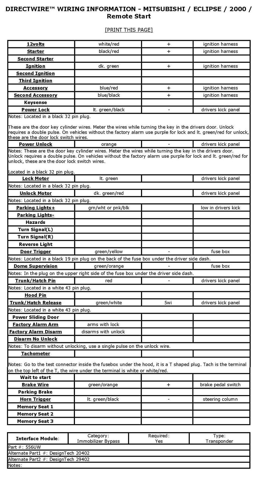
My car is Mitsubishi Eclipse 2000GS. Here is below the description that I guided for connecting my alarm.
And here is questions:
1. Output Harness Ignition 3/ Active Output
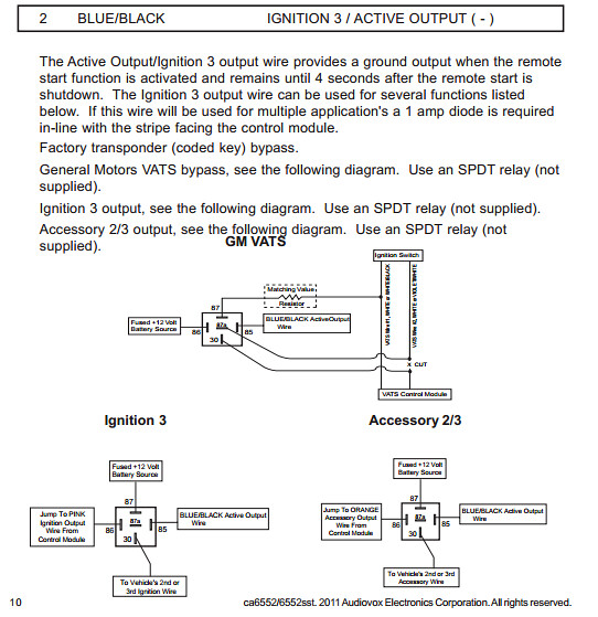
As in manual said it's additional wire that can be programmed for different purpose especially for transporder bypass. And as I wish to install car alarm remote I understand that I need it. But as I looked on my wire diagram (Start and Immobilizer ) I can't find to which wire I need to contact it.
Here is below the picture what's manual said about this:
Let's start I bought this alarm Code Alarm CA6552 for good reference and nice price compare to DEI models. Anyway the install and guide that was provided as I understood is not easy for person who install it first.
Here is the clickable link with specification
My car is Mitsubishi Eclipse 2000GS. Here is below the description that I guided for connecting my alarm.
And here is questions:
1. Output Harness Ignition 3/ Active Output
As in manual said it's additional wire that can be programmed for different purpose especially for transporder bypass. And as I wish to install car alarm remote I understand that I need it. But as I looked on my wire diagram (Start and Immobilizer ) I can't find to which wire I need to contact it.
Here is below the picture what's manual said about this:
 So do I need to cut my starter cable and connect this like it on image 3 for remote start option
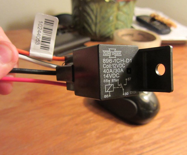
Here is the picture of what relay I have with this alarm
So do I need to cut my starter cable and connect this like it on image 3 for remote start option
Here is the picture of what relay I have with this alarm
 *********************************************************
2. Output Harness AUX 1
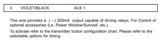
It's provides impulse signal to control my power window, sunroof etc. But I really don't know how and what I need to do with this wire. Here below description of it
*********************************************************
2. Output Harness AUX 1
It's provides impulse signal to control my power window, sunroof etc. But I really don't know how and what I need to do with this wire. Here below description of it
 *********************************************************
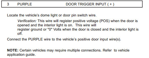
3. Input Harness Door trigger input+
According to my electric diagram we have negative switch it's mean both wires from key cylinder has ground, so should I just cut this wire or I misunderstood the purpose of it
*********************************************************
3. Input Harness Door trigger input+
According to my electric diagram we have negative switch it's mean both wires from key cylinder has ground, so should I just cut this wire or I misunderstood the purpose of it
 *********************************************************
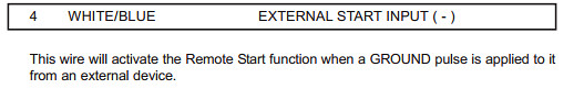
4. Input Harness External Start Input (-)
Should I connect it to one of my ground wire on bypass kit DEI 556U. Right ?
*********************************************************
4. Input Harness External Start Input (-)
Should I connect it to one of my ground wire on bypass kit DEI 556U. Right ?
 *********************************************************
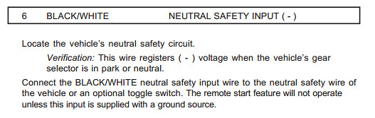
5. Input Harness Neutral Safety Input(-)
It's necessary for remote start, and couldn't locate this wire. Is it in big junction box ?
*********************************************************
5. Input Harness Neutral Safety Input(-)
It's necessary for remote start, and couldn't locate this wire. Is it in big junction box ?
 *********************************************************
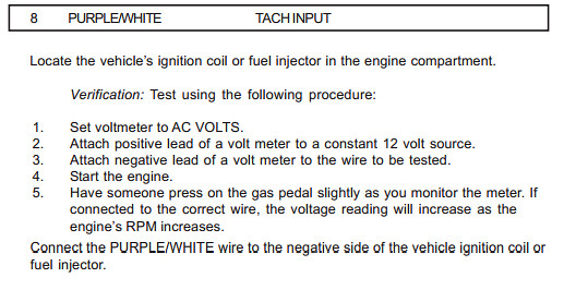
]6. Input Harness Tach Input
As professional guide side of wiring location the picture from the top thread which I followed it's some plug in my fuse box, can't locate it definitely so need help to find it.
Here is what alarm guide said :
*********************************************************
]6. Input Harness Tach Input
As professional guide side of wiring location the picture from the top thread which I followed it's some plug in my fuse box, can't locate it definitely so need help to find it.
Here is what alarm guide said :
 *********************************************************
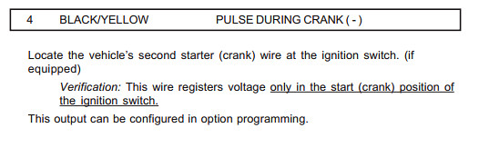
7.Alternate Output Harness - Pulse during crank
Should I connect it just to starter wire, because as I understood I haven't second starter wire, and what actually this alarm wire doing.
*********************************************************
7.Alternate Output Harness - Pulse during crank
Should I connect it just to starter wire, because as I understood I haven't second starter wire, and what actually this alarm wire doing.
 *********************************************************
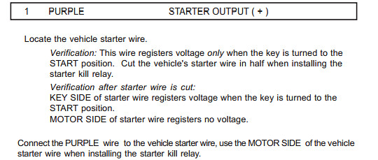
8.Start Harness - Starter Output(+)
According to manual I should install starter killer, here where I should use this wire Ignition 3 from output harness. Right ? And is it really necessary to install this starter killer because I've immobilizer ?
*********************************************************
8.Start Harness - Starter Output(+)
According to manual I should install starter killer, here where I should use this wire Ignition 3 from output harness. Right ? And is it really necessary to install this starter killer because I've immobilizer ?
 *********************************************************
So here we have pretty a lot of question that I wish to figure out for myself and I wish to help people who going to have probably the same question with DIY Car Alarm.
And one more time the list of questions:
1. Output Harness Ignition 3/ Active Output
2. Output Harness AUX 1
3. Input Harness Door trigger input+
4. Input Harness External Start Input (-)
5. Input Harness Neutral Safety Input(-)
6. Input Harness Tach Input
7.Alternate Output Harness - Pulse during crank
8.Start Harness - Starter Output(+)
THE MAIN THREAD GOING BE UPDATED WHILE I'LL GET ANSWERS ON MY QUESTION AND EVERYTHING WOULD BE CLEAR.
So will do Small How To DIY Car Alarm in future from this thread
Thanks everybody who going to help me in this !!!;)
And here is questions:And here is questions:The degree of your luck depends on your willingness to act
*********************************************************
So here we have pretty a lot of question that I wish to figure out for myself and I wish to help people who going to have probably the same question with DIY Car Alarm.
And one more time the list of questions:
1. Output Harness Ignition 3/ Active Output
2. Output Harness AUX 1
3. Input Harness Door trigger input+
4. Input Harness External Start Input (-)
5. Input Harness Neutral Safety Input(-)
6. Input Harness Tach Input
7.Alternate Output Harness - Pulse during crank
8.Start Harness - Starter Output(+)
THE MAIN THREAD GOING BE UPDATED WHILE I'LL GET ANSWERS ON MY QUESTION AND EVERYTHING WOULD BE CLEAR.
So will do Small How To DIY Car Alarm in future from this thread
Thanks everybody who going to help me in this !!!;)
And here is questions:And here is questions:The degree of your luck depends on your willingness to act


Welcome to the forum! There are many members that can assist you with your install. While CodeAlarm is not my usual brand, I can answer
some of your questions.First, understand that the CA6552 is a generic aftermarket unit that is designed to be flexible enough to handle most normal vehicles. Not all
wires will be necessary. Notice that there are both (+) and (-) Door Trigger Inputs. Depending on the vehicle, only one of them will be used.Second, it appears that the CA6552 system is an alarm / remote start / keyless entry unit. For the remote start portion to work, I believe you
will need a transponder bypass module. Looks like Mitsubishi started incorporating transponders into the Eclipse in 2000. You can verify this by wrapping your keyhead in several layers of aluminum foil and trying to start your car. There doesn't appear to be any data style units for your car so you will need a spare key and a universal transponder bypass module like the DEI 556UW.To answer your first question, the Blue/Black Ign3 wire would be used to control the bypass module, if one is required. It does have other
uses depending on the vehicles' needs.The second answer is: Your car has one Ignition wire, one Starter wire and two Accessory wires. While you could use the supplied relay
for that, an easier way is to program the Pink/White Ignition2 wire to Accessory2 and use that Pink/White wire for the vehicles ACC2 wire.Typically the AUX's are optional. They can be used to do various things like widow open & close, turn on the defroster, etc.
Soldering is fun!
Howard, it's way past your bedtime...  My condolences on the loss.
Here are some more answers. ( I was typing whilst the U.K was busy...)
Before we get to far, be advised that this unit is designed to be installed into a vehicle with an Automatic Transmission. If you have a
manual transmission, stop right here and purchase a system that is designed and safe for a manual transmission.The External Start Input won't be used for your install. However you could use it to test a remote startup without the CA's remotes by
touching this wire to chassis ground.The Neutral Safety Input should be connected to an ECM wire that shows (-) when the transmission is in Park or Neutral. On your car,
Code Alarm data has this info : Neutral Safety BLACK/ RED (-) PARK AND NEUTRAL SWITCH On some vehicles, it is connected to the Parking Brake wire.Most installers have found that running in Tach Mode provides the most reliable starting. The Tach Input wire should be connected to a
good Tach source. The DEI info you listed has a tach source listed. Connect to that wire, program the CA6552 for Tach Mode operationand perform the Tach Learn procedure.Pulse During Crank probably won't be necessary.
The Purple Starter Output can be connected directly to the vehicles Starter wire at the ignition switch harness. If you want Starter-Kill, then
follow the instructions and install the supplied relay. Soldering is fun!kreg357 wrote:
|
Ken;3301473 wrote:
|
 Printable version
| You cannot post new topics in this forum You cannot reply to topics in this forum You cannot delete your posts in this forum You cannot edit your posts in this forum You cannot create polls in this forum You cannot vote in polls in this forum |

| Search the12volt.com |

Saturday, April 27, 2024 • Copyright © 1999-2024 the12volt.com, All Rights Reserved • Privacy Policy & Use of Cookies

