the12volt.com spacer
icon

2012 optima pts, viper responder one


Post ReplyPost New Topic
< Prev Topic Next Topic >
chaseacej 
Member - Posts: 11
Member spacespace
Joined: November 25, 2012
Location: North Dakota, United States
Posted: December 09, 2012 at 3:18 PM / IP Logged  
I am trying to install a Viper Responder One on a 2012 Optima PTS. I have gotten all of the wires hooked up i believe to be correctly. When I try to activate the trigger wire the ignition turns on but the starter will not engage. I get about 150mV on the starter wire shown in the fortin evo-all guide.
Does it seem odd that you connect a large 30A output to starter wire to the small gray wire in the car? Is the gray wire just an output wire to engage the starter?
Any help would be appreciated.
Thanks.
kreg357 
Platinum - Posts: 7,783
Platinum spaceThis member has made a donation to the12volt.com. Click here for more info.spaceThis member has been recognized as an authority in Electrical Theory. Click here for more info.spaceThis member has been recognized as an authority in Mobile Security and Convenience. Click here for more info.spacespace
Joined: January 30, 2009
Location: Pennsylvania, United States
Posted: December 09, 2012 at 4:00 PM / IP Logged  

Not too odd for an aftermarket remote starter unit to have thick ignition wires.  These units were designed to

support a wide variety of vehicles and all the older cars needed the thick wires while some of the newer vehicles
don't. 

Did you connect all the Vipers' fused power wires to +12V constant.  Not familiar with the Viper Responder One

unit but going by the install guide in the Downloads section there appear to be two Red power wires.

Did you connect the EVO-ALL to the Viper in the W2W mode?

Did the EVO-ALL respond properly during programming?

Do the other functions ( lock, unlock, trunk release, etc ) work OK?

Did you connect the Viper Neutral Safety Switch wire to chassis ground if the Optima is an Auto Trans vehicle?

Did you plug in and turn to ON the NSS?

Soldering is fun!
chaseacej 
Member - Posts: 11
Member spacespace
Joined: November 25, 2012
Location: North Dakota, United States
Posted: December 09, 2012 at 4:10 PM / IP Logged  
Have both the red +12V connected.
Connected in W2W mode.
The EVO-ALL programmed correctly.
Its only a remote start system so all the smartkey functions still work.
I have the neutral safety switch grounded, forgot this initially.
NSS assuming that is the neutral safety switch?
I havent tried to see what the gray starter wire gets for voltage by a normal start yet.
When I ground the activate wire the ignition will turn on and the doors will unlock. Waits at this for a few seconds then locks the doors and rearms the system.
kreg357 
Platinum - Posts: 7,783
Platinum spaceThis member has made a donation to the12volt.com. Click here for more info.spaceThis member has been recognized as an authority in Electrical Theory. Click here for more info.spaceThis member has been recognized as an authority in Mobile Security and Convenience. Click here for more info.spacespace
Joined: January 30, 2009
Location: Pennsylvania, United States
Posted: December 09, 2012 at 4:40 PM / IP Logged  

Sounds good. 

Did you connect the EVO-ALL Dark Blue (-) While Running wire to the Vipers'   BLUE STATUS OUTPUT wire on the

4-pin satellite harness?

Did you program the Viper to Tach Mode and do the Tach Learn process?

Soldering is fun!
chaseacej 
Member - Posts: 11
Member spacespace
Joined: November 25, 2012
Location: North Dakota, United States
Posted: December 09, 2012 at 4:42 PM / IP Logged  
That was one wire I wasnt sure if it was right but i do have those two connected.
I havent programmed the Viper to tach mode yet. I will give that a try.
chaseacej 
Member - Posts: 11
Member spacespace
Joined: November 25, 2012
Location: North Dakota, United States
Posted: December 09, 2012 at 5:10 PM / IP Logged  
Went through the tach learn on the viper and still nothing.
I checked the gray start wire voltage at normal start and didnt get much from that although my meter is pretty slow.
chaseacej 
Member - Posts: 11
Member spacespace
Joined: November 25, 2012
Location: North Dakota, United States
Posted: December 09, 2012 at 5:22 PM / IP Logged  
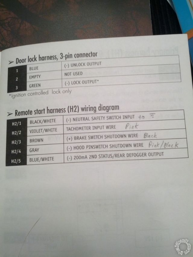
This shows what wires i have connected where on the viper.
2012 optima pts, viper responder one -- posted image.
kreg357 
Platinum - Posts: 7,783
Platinum spaceThis member has made a donation to the12volt.com. Click here for more info.spaceThis member has been recognized as an authority in Electrical Theory. Click here for more info.spaceThis member has been recognized as an authority in Mobile Security and Convenience. Click here for more info.spacespace
Joined: January 30, 2009
Location: Pennsylvania, United States
Posted: December 09, 2012 at 6:57 PM / IP Logged  

All looks good.  Can't think of anything else, unless you have the connections to the CAN wires reversed.

Does the Viper give any type of failed remote start Shutdown Diagnostic output ?

Soldering is fun!
chaseacej 
Member - Posts: 11
Member spacespace
Joined: November 25, 2012
Location: North Dakota, United States
Posted: December 09, 2012 at 7:26 PM / IP Logged  
Did the shutdown diagnostics and am getting the + brake shutdown code.
chaseacej 
Member - Posts: 11
Member spacespace
Joined: November 25, 2012
Location: North Dakota, United States
Posted: December 09, 2012 at 7:43 PM / IP Logged  
i unhooked the brake wire and now the car will remote start. However, when I enter the vehicle and press the pts button twice to turn on the ignition it will turn amber for acc, then off. I cannot shut the car down with the pts button. I have to use the viper remote.
Page of 2

  Printable version Printable version Post ReplyPost New Topic
You cannot post new topics in this forum
You cannot reply to topics in this forum
You cannot delete your posts in this forum
You cannot edit your posts in this forum
You cannot create polls in this forum
You cannot vote in polls in this forum

  •  
Search the12volt.com
Follow the12volt.com Follow the12volt.com on Facebook
Tuesday, May 7, 2024 • Copyright © 1999-2024 the12volt.com, All Rights Reserved Privacy Policy & Use of Cookies
Disclaimer: *All information on this site ( the12volt.com ) is provided "as is" without any warranty of any kind, either expressed or implied, including but not limited to fitness for a particular use. Any user assumes the entire risk as to the accuracy and use of this information. Please verify all wire colors and diagrams before applying any information.

Secured by Sectigo
the12volt.com spacer
Support the12volt.com
Top
the12volt.com spacer