


relay behavior


Posted: April 28, 2014 at 7:12 PM / IP Logged
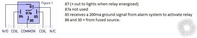 good day folks, here is the situation i need to resolve. i am using a relay to issue a + to a lighting system on my car. the relay is signaled by my alarm system issuing a -200MA ground. my issue. ive set the relay so that when triggered by a ground, it will output a + to the system. my problem is that there is a + feedback on the pin that is receiving the ground signal when the alarm system is sending the ground. ive tried to put a diode, but it will either block all signal or prevent the - to enter will keeping the + on the other side. what would be the way to fix this?
thank you
Eric
good day folks, here is the situation i need to resolve. i am using a relay to issue a + to a lighting system on my car. the relay is signaled by my alarm system issuing a -200MA ground. my issue. ive set the relay so that when triggered by a ground, it will output a + to the system. my problem is that there is a + feedback on the pin that is receiving the ground signal when the alarm system is sending the ground. ive tried to put a diode, but it will either block all signal or prevent the - to enter will keeping the + on the other side. what would be the way to fix this?
thank you
Eric

Posted: April 29, 2014 at 12:23 AM / IP Logged
Posted: April 29, 2014 at 5:30 AM / IP Logged
Posted: April 29, 2014 at 5:42 AM / IP Logged
Posted: April 29, 2014 at 5:45 AM / IP Logged
Posted: April 29, 2014 at 9:15 AM / IP Logged
Posted: April 29, 2014 at 5:47 PM / IP Logged
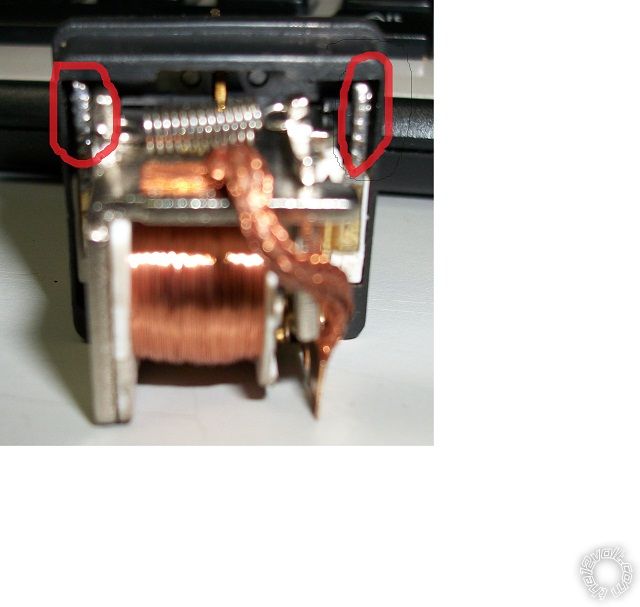 Good day, ive tried with a n4004 with one leg on each of these red spot that have solder on them and what seems to be the coil wire soldered on it. still no luck, with my test light, im still seeing a +12v signal on the input signal.
Posted: April 29, 2014 at 8:29 PM / IP Logged
Posted: April 29, 2014 at 11:35 PM / IP Logged
Posted: May 02, 2014 at 11:25 AM / IP Logged
 Printable version
| You cannot post new topics in this forum You cannot reply to topics in this forum You cannot delete your posts in this forum You cannot edit your posts in this forum You cannot create polls in this forum You cannot vote in polls in this forum |

| Search the12volt.com |
Follow the12volt.com 
Sunday, May 5, 2024 • Copyright © 1999-2024 the12volt.com, All Rights Reserved • Privacy Policy & Use of Cookies

Sunday, May 5, 2024 • Copyright © 1999-2024 the12volt.com, All Rights Reserved • Privacy Policy & Use of Cookies
Disclaimer:
*All information on this site ( the12volt.com ) is provided "as is" without any warranty of any kind, either expressed or implied, including but not limited to fitness for a particular use. Any user assumes the entire risk as to the accuracy and use of this information. Please
verify all wire colors and diagrams before applying any information.
