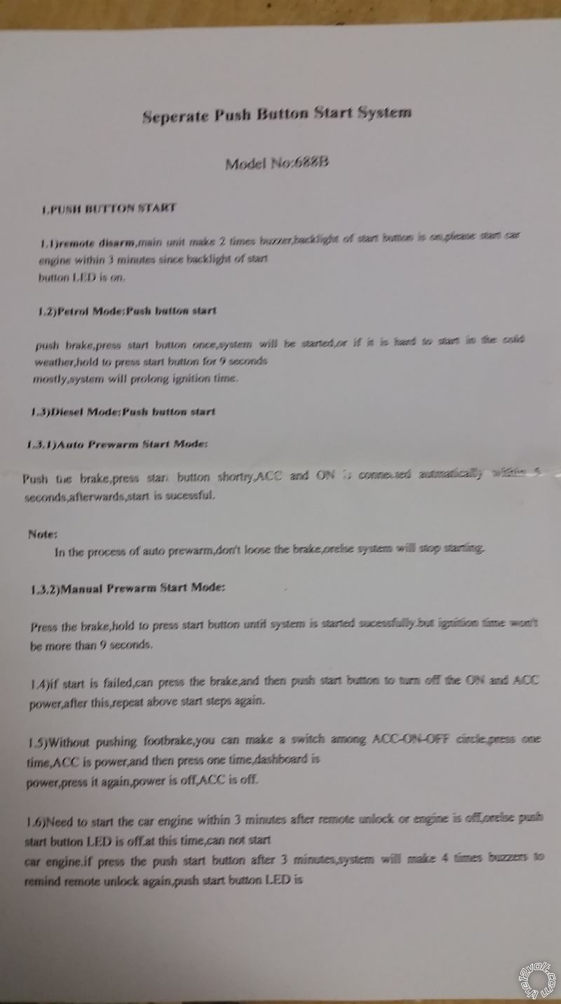
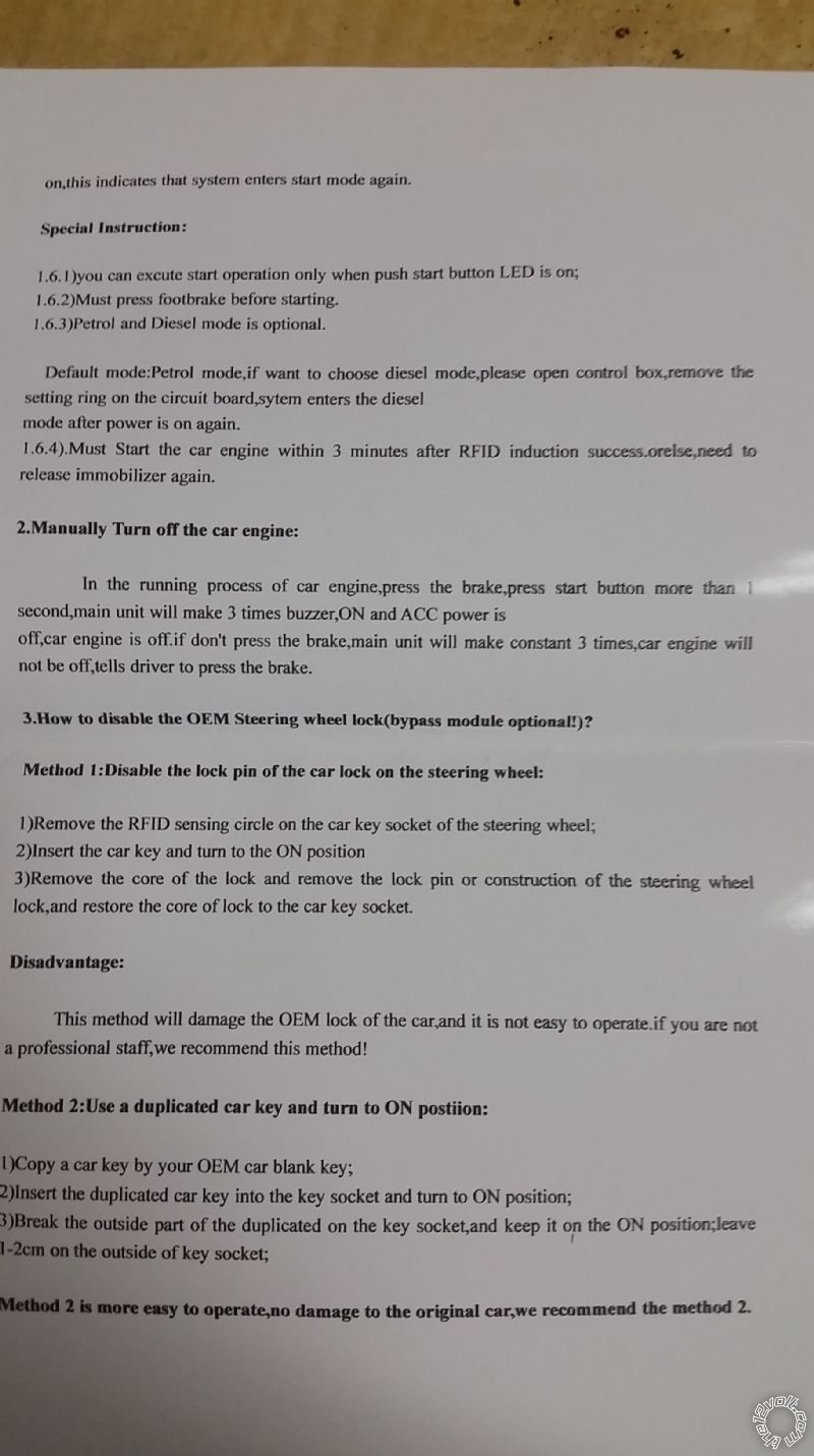
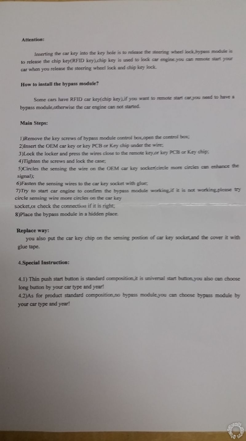
These are the remaining directions that were received with the push button start system. One page is for a bypass module but that doesn't apply to my setup since it is being installed on a 1967 Camaro with no such feature. The electric door lock system was from Klassic Keyless. So far the door lock system works great.
As you can see from the attached directions for the push button start system, they discuss function of the system as opposed to installation. I hope this is helpful. At first glance of the directions it looks like it was translated from Chinese to English by someone who doesn't have a firm grasp on the English language.
I think I'm picking up what you are laying down.
I tested the door lock actuator wires before I put my door panels back on. There is a blue wire and green wire running to the door lock actuator. When I hit the lock button the blue wire has power. When I hit the unlock button the green wire has power.
If I understand correctly, the system only sends a pulse of electricity through the green wire to unlock the door. When I hit the lock button the system sends a pulse of electricity to the blue wire to lock the door. When one wire receives a (+) signal the other wire is grounded. After each cycle, both wires are resting in a (-) state.
Your suggestion is to hook up the Unlock Signal (+) GREEN/ black wire from the push button start system to the green wire on the door lock actuator correct? This way when the unlock button is pressed on the remote, the green wire on the door lock actuator receives a (+) signal thus triggering a (+) signal to the Unlock Signal (+) GREEN/ black wire on the push button start system. I would then assume that the push button start system computer control would only need that single (+) signal to activate and turn on in a ready state so when I get in the car, I simply push the start button to turn on the car.
You also suggest hooking up the Lock Signal (-) blue/black wire from the push button start system to the same green wire on the door lock actuator correct? This way when the lock button is pressed on the remote, the green wire on the door lock actuator receives a (-) signal thus triggering a (-) signal to the Lock Signal (-) blue/black wire on the push button star system, correct? I would then assume that the push button start system computer control would only need that single (-) signal to deactivate and turn off the power to the push button start system so when I try to push the start button there is no power and thus the car will not turn on.
But that would mean that both the Unlock Signal (+) and Lock Signal (-) would receive the same (+) signal when the door is unlocked and the same (-) signal when the door is locked, correct? My only question would be whether or not that screws with the computer that controls the on/off function of the push button start system. Not sure if it would but I guess trial and error would tell.
I am just hesitant to connect both wires to the same door lock actuator wire and they both receive a (+) and a (-) signal at the same time. I wouldn't want to fry the computer control module or anything.
I would also be concerned that if it was hooked up as discussed above, what would happen if I turned the car on and then used the same remote to lock the car doors? Would the car die? I guess I could manually lock the doors but that would prove to be a hassle. I guess I could always wire a different fixed button somewhere in the car that would have lock and unlock the doors?
I greatly appreciate your assistance with working through this with me. I just want to make sure I know where I am wiring everything before I cut apart my harness so that I can make this process as smooth as possible.


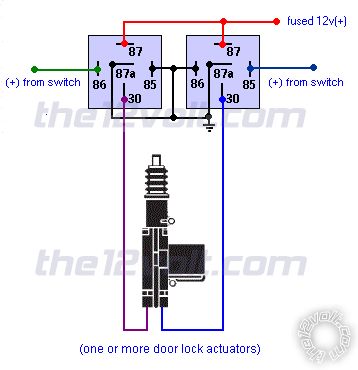 I was provided the reverse polarity wiring diagram from the tech at Innovative Ignition Systems but it looks like there is a lock signal (+) coming out of both relays.
I assume if I hook up the Unlock Signal (+) to the positive wire when I unlock the door, this will activate the push button start system so I can get in the car, push the button and start. But if I lock the doors once the car is started, the polarity to the unlock signal (+) wire will become (-), so will my car turn off?
I'm just trying to figure out how to wire this thing so when I unlock the door, I can get in and push the start button to start the car. When I am in the car, I will also like to lock the doors with the same remote without my car turning off. When I exit the car, I want to ensure that the push button start system is deactivated so if someone breaks into my car, they can't just push the start button and drive off. Please let me know if there are any suggestions or if I need to provide any other information, documents, pictures, diagrams, etc. Thank you in advance for the help!
I was provided the reverse polarity wiring diagram from the tech at Innovative Ignition Systems but it looks like there is a lock signal (+) coming out of both relays.
I assume if I hook up the Unlock Signal (+) to the positive wire when I unlock the door, this will activate the push button start system so I can get in the car, push the button and start. But if I lock the doors once the car is started, the polarity to the unlock signal (+) wire will become (-), so will my car turn off?
I'm just trying to figure out how to wire this thing so when I unlock the door, I can get in and push the start button to start the car. When I am in the car, I will also like to lock the doors with the same remote without my car turning off. When I exit the car, I want to ensure that the push button start system is deactivated so if someone breaks into my car, they can't just push the start button and drive off. Please let me know if there are any suggestions or if I need to provide any other information, documents, pictures, diagrams, etc. Thank you in advance for the help!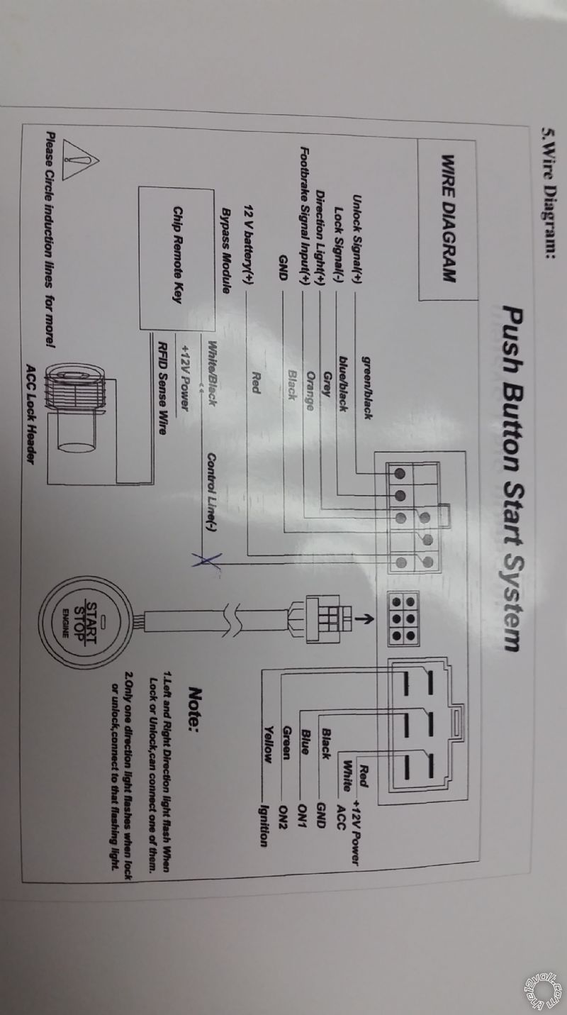


 the12volt
  Printable version


