the12volt.com spacer
icon

535T window automation


Post ReplyPost New Topic
< Prev Topic Next Topic >
alfa/resto 
Member - Posts: 7
Member spacespace
Joined: November 07, 2016
Location: California, United States
Posted: November 07, 2016 at 7:04 PM / IP Logged Link to Post Post Reply Quote alfa/resto
This is my first post here and will be starting with an electrical 101 question regarding the 535T. In all of the diagrams, the switch has only two connections for the motor/unit. What other wires are required on the switch so that I can run the motor forward and backward?
Note I'm using only the term motor...for now. Background on my project. I have a Chrysler Crossfire which has an automatic rear spoiler which I will be selling. I now have a SRT6 Crossfire which came with a clunky solid rear spoiler and want to switch it to an eBay automatic one - which I currently have on my dining table. I'll add that switching the units isn't a problem, but getting the motor as well as the limiting switches working is the problem. (I am a member of the Crossfire (XF) Forum, but I'm not getting much/any help from the group on this project.)
For now I'm working on just the motor - which is essentially the same as on a two wire automatic window motor - and have to admit I'm completely reliant on wiring diagrams. For now I have the wiring set-up with the Type B System which uses a SPDT relay.
I have what I believe is a correct switch which has four spade posts but with the outer two permanently connected to the other outer connections. It would be nice to post a photo.
I will admit that if/when I get the motor working with a switch (it goes up and down when switching the wires), I'll be asking about how to include the three wire limit switches in tandem to the motor.
Biba
Irwindale, CA
howie ll 
Pot Metal - Posts: 16,466
Pot Metal spacespace
Joined: January 09, 2007
Location: United Kingdom
Posted: November 08, 2016 at 11:40 AM / IP Logged Link to Post Post Reply Quote howie ll
Right for starters the motor should be wired as a type A.
Get a Spal window switch to complete or a double pole changeover centre off to complete.
When not in use both motor wires connect to ground.
For up,one wire goes "hot" whilst the other stays at ground.
For down you're simply reversing the process.
alfa/resto 
Member - Posts: 7
Member spacespace
Joined: November 07, 2016
Location: California, United States
Posted: November 08, 2016 at 1:52 PM / IP Logged Link to Post Post Reply Quote alfa/resto
howie II, thank you for replying. You mention not being a free install service. I would be happy to pay you (PayPal) if you can guide me through the switch wiring - and better yet, also assist me regarding the limit switches.
I will add that the 2005 SRT6 Crossfire's BCM does not contain a program for an electrical driven spoiler.
I do have a Spal type switch (is there a good reason they have to be so deep?), along with two SPDT Bosch relays (I can easily get more).
Biba
Irwindale, CA
howie ll 
Pot Metal - Posts: 16,466
Pot Metal spacespace
Joined: January 09, 2007
Location: United Kingdom
Posted: November 08, 2016 at 5:04 PM / IP Logged Link to Post Post Reply Quote howie ll
You won't need the relays assuming the motor draws 15 amps or less. Can you provide either a photo or a drawing of the back of the Spal switch.
Alternatively you could do this with a single pole double throw switch.
alfa/resto 
Member - Posts: 7
Member spacespace
Joined: November 07, 2016
Location: California, United States
Posted: November 08, 2016 at 8:08 PM / IP Logged Link to Post Post Reply Quote alfa/resto
My switch has ABCDEL. I've just tried using only the switch. Checking continuity I get A/E & A/D. With + on A and separate wires to both motor terminals. Nada. It is possible I have a bad switch.
I would like to use a relay since the wires from the switch to the motor will be about 15 feet. And I'd like to use the 535T since I feel it 'might' be possible to include the limit switches.
Biba
Irwindale, CA
howie ll 
Pot Metal - Posts: 16,466
Pot Metal spacespace
Joined: January 09, 2007
Location: United Kingdom
Posted: November 09, 2016 at 12:49 AM / IP Logged Link to Post Post Reply Quote howie ll
That tells me nothing! Photo or drawing please.
alfa/resto 
Member - Posts: 7
Member spacespace
Joined: November 07, 2016
Location: California, United States
Posted: November 09, 2016 at 1:42 PM / IP Logged Link to Post Post Reply Quote alfa/resto
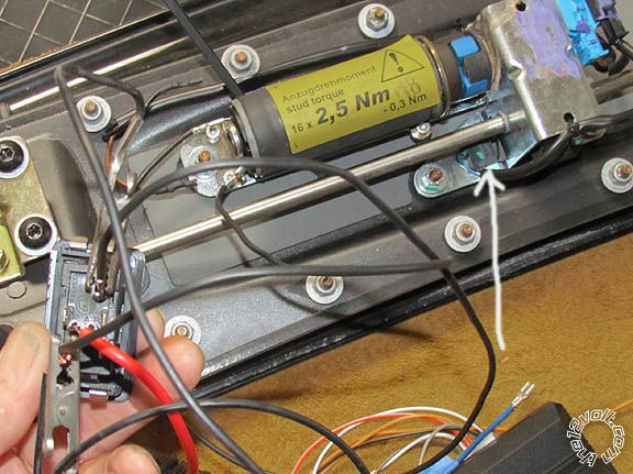
I finally found where the attachment link was. Not too much to see except you get to see the spoiler's set-up. As I said, red + (from 12V battery) is on A; black wires from continuity with D to + motor contact; black wires from continuity E to – motor contact.
Note: white arrow points to basic down limit switch.
535T window automation -- posted image.
Biba
Irwindale, CA
alfa/resto 
Member - Posts: 7
Member spacespace
Joined: November 07, 2016
Location: California, United States
Posted: November 09, 2016 at 5:34 PM / IP Logged Link to Post Post Reply Quote alfa/resto
I'm sure the geared window motors are also quite stiff (for wont of a better term). I'm getting the motor to partially turn, but almost immediately it blows the fuse. Last one was a 30 amp. This was another reason I want/need to use a relay unless you have a better idea.
I somewhat screwed up the motor - though feel I can fix it - but have ordered another one on eBay.
Biba
Irwindale, CA
howie ll 
Pot Metal - Posts: 16,466
Pot Metal spacespace
Joined: January 09, 2007
Location: United Kingdom
Posted: November 10, 2016 at 1:13 AM / IP Logged Link to Post Post Reply Quote howie ll
Forget the switch just take the motor wires to a 535t or a Spal switch bluntly you're wiring it wrong every time by making wrong assumptions.
alfa/resto 
Member - Posts: 7
Member spacespace
Joined: November 07, 2016
Location: California, United States
Posted: November 10, 2016 at 1:12 PM / IP Logged Link to Post Post Reply Quote alfa/resto
howie II, that is why I am asking how to wire up the switch - and/or the 535T.
I had the SRT wired exactly like the upper diagram with a relay on page 20. However, I do/did not know what type of switch to use for this and what specific numbers or letters to connect the three wires going to it. That is all that I was asking regarding how to complete that type of circuit.
I did not use the brand Spal but the switch I have has the same number of spade contacts, in the same location with the same lettering. I am very sure that using just the switch will never work.
If you're telling me to use a Spal switch in conjunction with the 535T unit on page 20 with the relay, please tell me the specific letter where the BROWN / Violet wires are attached; what letter the 30 from the relay wire is attached; what number directly from the down contact on the motor is attached.
Once I have that, I'll take it from there - going on the basis it should work or that the motor draws too many amps for the 535T to handle.
Biba
Irwindale, CA
Page of 2

  Printable version Printable version Post ReplyPost New Topic
You cannot post new topics in this forum
You cannot reply to topics in this forum
You cannot delete your posts in this forum
You cannot edit your posts in this forum
You cannot create polls in this forum
You cannot vote in polls in this forum

  •  
Search the12volt.com
Follow the12volt.com Follow the12volt.com on Facebook
Saturday, April 27, 2024 • Copyright © 1999-2024 the12volt.com, All Rights Reserved Privacy Policy & Use of Cookies
Disclaimer: *All information on this site ( the12volt.com ) is provided "as is" without any warranty of any kind, either expressed or implied, including but not limited to fitness for a particular use. Any user assumes the entire risk as to the accuracy and use of this information. Please verify all wire colors and diagrams before applying any information.

Secured by Sectigo
the12volt.com spacer
Support the12volt.com
Top
the12volt.com spacer