the12volt.com spacer
icon

2006 tsx viper remote start


Post ReplyPost New Topic
< Prev Topic Next Topic >
m109ner 
Copper - Posts: 51
Copper spacespace
Joined: December 10, 2007
Location: Illinois, United States
Posted: December 12, 2007 at 1:05 PM / IP Logged  

I'm installing a Viper 160XVL remote start unit int o my 2006 Acura TSX.  I'll also be using an idatalink ADS-DLSL-HA.  I'm installed simler rs units, alarms, stereos, etc.  But this oen is a bit more invloved than I thought.  I'm not afraid to tackle it.  ACtually looking forward to the install.  Just tryign to make sure that I have all my ducks in a row. 

I've pretty much maped out all the wiring between the Viper unit and the idatalink unit with the exception of the following:

*Ground-out when running

*Starter (+) Input

*Lock (-) and unlock (-)

The viper 160xvl comes with two wires for security arm (-) and disarm (-).  Are these to be used as the lock/unlock wires to connec to the idatalink  box lock and unlock wires?  The XVL also comes with a door lock harnes (DEI 451M), but this has 5 wires not 2.  This is where my confusion lies in with the lock/unlock wire connections.

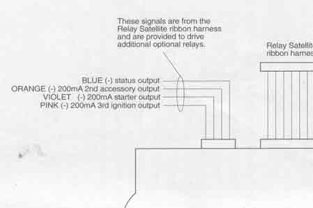
The XVL has status output, 2nd ACC output, 200mA output, and 200mA 3rd ignition.  Not sure what thes are for.

Any help you guys can offer I would really appreciate it.  :)

tedmond 
Gold - Posts: 4,610
Gold spaceThis member has been recognized as an authority in Mobile Security and Convenience. Click here for more info.spacespace
Joined: January 06, 2007
Location: Ontario, Canada
Posted: December 12, 2007 at 2:52 PM / IP Logged  

1*Ground-out when running

2*Starter (+) Input

3*Lock (-) and unlock (-)

4*security arm (-) and disarm (-)

1)ground out when running (aka status output from XVL) is used to turn on devices such as bypass modules or your idatalink  ADS-DLSL-HA

2)not sure what the starter (+) input is. Are you sure this is not labeled as Starter (+) output?

3)lock on tsx (-) - Pink in drivers kick panel in a GREEN CONNECTOR

unlock on tsx (-) - Light Blue in drivers kick panel in a GREEN CONNECTOR

**note you can only test the wires in drivers kick panel from using facotry door lock switch on passenger side**

4)Security Arm (-) - WHITE/ Red in Driver door in the door molex (plug)

   Security Disarm (-) - White in Driver door in door molex (plug)
* you must remove door panel to get access to these wires*

The viper 160xvl comes with two wires for security arm (-) and disarm (-).  Are these to be used as the lock/unlock wires to connec to the idatalink  box lock and unlock wires?  The XVL also comes with a door lock harnes (DEI 451M), but this has 5 wires not 2.  This is where my confusion lies in with the lock/unlock wire connections.

the security arm/disarm is not your unlock/lock wires. The idatlink should take care of the factory disarm/arm, lock and unlock wires. if the unit does not work, refer to the wiring i left above. The 451m is not required since the doors are just negative triggers. As mentioned before, your idatalink SHOULD take care of locks and factory alarm.

The XVL has status output, 2nd ACC output, 200mA output, and 200mA 3rd ignition.  Not sure what thes are for.

status output is aka GROUND OUT WHEN RUNNING. the 200ma outputs are not required unless u need to drive an extra relay for ignition, acc or starter. From my wiring diagram, it shows u only have one ignition, accessory and one start, so using the ones off the relay pack should be no proble,

good luck, if u have any more questions please ask. ps sorry if i made it hard to undersatnd or lost you along the way.

m109ner 
Copper - Posts: 51
Copper spacespace
Joined: December 10, 2007
Location: Illinois, United States
Posted: December 12, 2007 at 4:17 PM / IP Logged  
tedmond wrote:

1)ground out when running (aka status output from XVL) is used to turn on devices such as bypass modules or your idatalink  ADS-DLSL-HA

Ok.  SO, connect ground ground out when running from idatalink to status output from XVL, correct?

tedmond wrote:
2)not sure what the starter (+) input is. Are you sure this is not labeled as Starter (+) output?

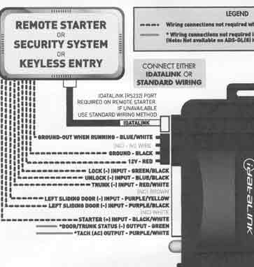
Yes I'm sure.  Please look at attached images.

idatalink madule:

2006 tsx viper remote start -- posted image.

Viper relay satellite module:

2006 tsx viper remote start -- posted image.

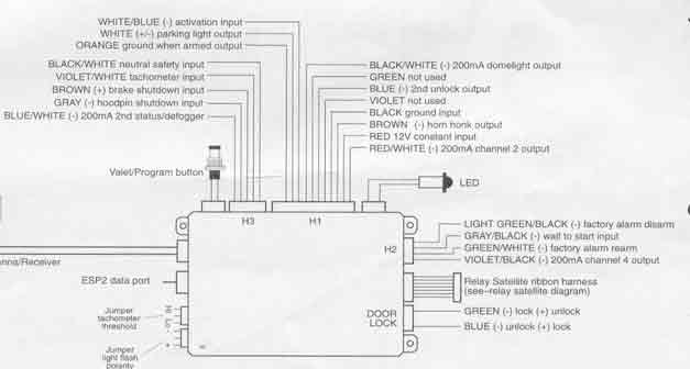
Viper Main brain box

2006 tsx viper remote start -- posted image.

tedmond wrote:
3)lock on tsx (-) - Pink in drivers kick panel in a GREEN CONNECTOR
unlock on tsx (-) - Light Blue in drivers kick panel in a GREEN CONNECTOR

**note you can only test the wires in drivers kick panel from using facotry door lock switch on passenger side**

Yes.  You're right.  But if you look at the idatalink image it shows this connection happening between the remote starter and the idatalink module.  ?????

tedmond wrote:
4)Security Arm (-) - WHITE/ Red in Driver door in the door molex (plug)
   Security Disarm (-) - White in Driver door in door molex (plug)
* you must remove door panel to get access to these wires*

Remove the door panel?  I was hoping to not have to get into the door.  That's why I bought the idatalink module.  Do I still need to get into the driver door (white & WHITE/ red)  to connect the arm/disarm wires from the XVL to.  If that's the case, then how does the idatalink unit play a roll in disarming and arming?  If the wires aren't connected to the idatalink unit?  That's what confuses me.

tedmond wrote:
the 200ma outputs are not required unless u need to drive an extra relay for ignition, acc or starter. From my wiring diagram, it shows u only have one ignition, accessory and one start, so using the ones off the relay pack should be no proble,

Cool!  So no need to use the 200ma outputs other than the status output which I'm connecting to the ground out when running wire of on the idatalink module, right?

Thanks for being so patient and expalining all this to me.  I really appreciate it.  That's why these forums are awesome.

tedmond 
Gold - Posts: 4,610
Gold spaceThis member has been recognized as an authority in Mobile Security and Convenience. Click here for more info.spacespace
Joined: January 06, 2007
Location: Ontario, Canada
Posted: December 12, 2007 at 6:16 PM / IP Logged  

1)Ok.  SO, connect ground ground out when running from idatalink to status output from XVL, correct?

yes that is correct. the idatalink will be triggered when the remote start is active.

2) start wire input from idatlink

after checking, connect your START wire from START wire on car to this wire. (just tap into wire) its used to disarm ur factory alarm system.

3) Yes.  You're right.  But if you look at the idatalink image it shows this connection happening between the remote starter and the idatalink module.  ????? Remove the door panel?  I was hoping to not have to get into the door.  That's why I bought the idatalink module.  Do I still need to get into the driver door (white & WHITE/ red)  to connect the arm/disarm wires from the XVL to.  If that's the case, then how does the idatalink unit play a roll in disarming and arming?  If the wires aren't connected to the idatalink unit?  That's what confuses me.

no need to go to your door. i only said that if your idatlink module didnt work. Simply connect your lock and unlock wires from the viper unit to the idatalink. Datalink will unlock and lock the doors for you, without having to tap into other factory wires. idatalink should for a fact do all required things for the acura. The idatalink plays a role in disarming and arming with the "START "wire input as mentioned before. when the unit detects that remote start is active (STATUS OUTPUT) and a START signal is sent, the unit tells the onboard car computer to disarm. this ensures the factory alarm will not wail on you.

4)Cool!  So no need to use the 200ma outputs other than the status output which I'm connecting to the ground out when running wire of on the idatalink module, right

That is correct. Cut all other connections that are not used and tape them up good. Just make sure you use the Status Output and wire that to the Ground out when running from your idatalink. Hope that answers all ur questions. Good luck, cheers !

m109ner 
Copper - Posts: 51
Copper spacespace
Joined: December 10, 2007
Location: Illinois, United States
Posted: December 12, 2007 at 8:07 PM / IP Logged  

Ok, I'm making some progress here.  Thanks.  :)

I'm good on the following:

*ground-out when running to status output from XVL
*2nd ACC output, 200mA output, and 200mA 3rd ignition (No need for these.  Just tape up.)

Not so good with the following:

Lock and Unlock I’m still not 100%.  Here’s why.  The Viper brain box has a “DOOR LOCK” plug for unlock and lock.  But what plugs into that plug is a wire harness (DEI 451M).  I;m sure you're familiar with it.  This is a 5 wire unit.  All five (thick) wires run into the relay and 3 (thin wires) run out to a white plug.  This plug, plugs into the Viper brain box.  Should I cut the 3 wires that lead to the plug (middle one has no use as mentioned in the wiring diagram above)?  The Green (-) lock (+) unlock, the blue (+) unlock (-) lock.  These are identified, in the diagram above, to have both polarities .

tedmond wrote:
start wire input from idatlink
[P]after checking, connect your START wire from START wire on car to this wire. (just tap into wire) its used to disarm ur factory alarm system.

Not sure I understand what “Start wire on car” you mean.  An ignition wire?  The starter wire?  The diagram shows the connection for these wires happening between the idatalink module and the remote starter.

tedmond 
Gold - Posts: 4,610
Gold spaceThis member has been recognized as an authority in Mobile Security and Convenience. Click here for more info.spacespace
Joined: January 06, 2007
Location: Ontario, Canada
Posted: December 12, 2007 at 9:10 PM / IP Logged  

1) Not so good with the following:

Lock and Unlock I’m still not 100%.  Here’s why.  The Viper brain box has a “DOOR LOCK” plug for unlock and lock.  But what plugs into that plug is a wire harness (DEI 451M).  I;m sure you're familiar with it.  This is a 5 wire unit.  All five (thick) wires run into the relay and 3 (thin wires) run out to a white plug.  This plug, plugs into the Viper brain box.  Should I cut the 3 wires that lead to the plug (middle one has no use as mentioned in the wiring diagram above)?  The Green (-) lock (+) unlock, the blue (+) unlock (-) lock.  These are identified, in the diagram above, to have both polarities .

I would probe (test with digital volt meter) and ensure its a ground that is sent out. if it (-) just cut the plug, and connect green and blue from the viper unit to the idatalink input wires for locking. make sure they are negative outputs from the viper unit. default is negative from the XVL brain. in some cases, the 451M will be needed. its only used in cars where there is a single wire door lock system, reverse polarity, vacuum doors, etc,

2)Not sure I understand what “Start wire on car” you mean.  An ignition wire?  The starter wire?  The diagram shows the connection for these wires happening between the idatalink module and the remote starter.

the START (+) input wire from the idatalink module, splice into the Starter wire on the car or Starter wire of the relay pack output. Does not matter if u make the connection between the car or remote start because the remote start wire is connected to the car start wire. either way, power will be sent through the set of wires anyways.


m109ner 
Copper - Posts: 51
Copper spacespace
Joined: December 10, 2007
Location: Illinois, United States
Posted: December 13, 2007 at 11:02 AM / IP Logged  

Ok,  Now I'm cool  with the starter input (+) wire.

Another question.  Both the idatalink and the Viper unit have tach wires.  idatalink unit is (AC) output, the Viper unit is an input.

Shuold I not use the Viper Tach input wire at all and just run the idatalink (AC) output to my car's ECPM/PCM tach terminal?

Thanks

tedmond 
Gold - Posts: 4,610
Gold spaceThis member has been recognized as an authority in Mobile Security and Convenience. Click here for more info.spacespace
Joined: January 06, 2007
Location: Ontario, Canada
Posted: December 13, 2007 at 3:15 PM / IP Logged  

well from experiance, i have only used the fortin can system for honda. I always had problems with the tach from forin modules and learned to never trsut them. i always go straight to the tach wire @ the coil or injector. i would test the output from the idatalink and wire that to your XVL tach input and see if it will start without a problem. If there is no problem, no need to run the wire to the Coil. Never really had experiance with idatalink tach, but it should be okay cuz they are the most reliable units out there.

and if u wanted to use idatalink, wire the idatlink tach output to the xvl input.

m109ner 
Copper - Posts: 51
Copper spacespace
Joined: December 10, 2007
Location: Illinois, United States
Posted: December 13, 2007 at 5:28 PM / IP Logged  

I called idatalink Tech Support and asked about the Tach(AC) output, Starter (+) inpput, Door/Trunk Status(-) output and the hood(-) output and they said connect them all to the starter wire.

They design and built it, so it's gotta be right.  Just not sure I understad the rationale.

Anyone care to chime in???

tedmond 
Gold - Posts: 4,610
Gold spaceThis member has been recognized as an authority in Mobile Security and Convenience. Click here for more info.spacespace
Joined: January 06, 2007
Location: Ontario, Canada
Posted: December 13, 2007 at 5:46 PM / IP Logged  

I called idatalink Tech Support and asked about the Tach(AC) output, Starter (+) inpput, Door/Trunk Status(-) output and the hood(-) output and they said connect them all to the starter wire.

i dont understand why they would tell u to connect the door/trunk outputs and connect them to ur start wire... Im for sure they meant to connect it to your starter unit the XVL. the purpose of the datalink is to reduce time and wiring. 2 wires that go to databus will control locks, door/hatch pins, tach, etc. usually it will be 2 wires to the car. From the 2 wires, data will be transfered and received through the datalink. from datalink connect outputs to the inputs of the XVL, and from XVL, connect outputs to idatalink inputs.

Page of 6

  Printable version Printable version Post ReplyPost New Topic
You cannot post new topics in this forum
You cannot reply to topics in this forum
You cannot delete your posts in this forum
You cannot edit your posts in this forum
You cannot create polls in this forum
You cannot vote in polls in this forum

  •  
Search the12volt.com
Follow the12volt.com Follow the12volt.com on Facebook
Saturday, April 27, 2024 • Copyright © 1999-2024 the12volt.com, All Rights Reserved Privacy Policy & Use of Cookies
Disclaimer: *All information on this site ( the12volt.com ) is provided "as is" without any warranty of any kind, either expressed or implied, including but not limited to fitness for a particular use. Any user assumes the entire risk as to the accuracy and use of this information. Please verify all wire colors and diagrams before applying any information.

Secured by Sectigo
the12volt.com spacer
Support the12volt.com
Top
the12volt.com spacer