


single switch, multiple outputs


Posted: September 14, 2010 at 11:59 PM / IP Logged


Posted: September 15, 2010 at 12:24 AM / IP Logged
Posted: September 15, 2010 at 8:19 AM / IP Logged
Posted: September 15, 2010 at 8:57 AM / IP Logged
Posted: September 15, 2010 at 9:40 AM / IP Logged
Posted: September 16, 2010 at 3:20 AM / IP Logged
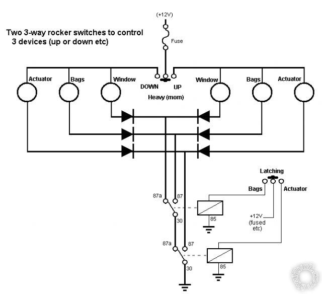 For example, if the "power" (upper) rocker can't handle the current, relays are required.
If the devices are not separate +12V windings or terminals, then alternate switching is required (eg - if +12V & GND are reversed and not merely +12V as shown).
And I do not like using diodes for "power" things - but up to 3A is usually ok. Above that, relay switching may be better.
Before getting in to better design I figured I'd merely post the above....
Maybe 6 relays are required.... (SPDT else DPDT etc)
And as I am about to order some FETs, I can't help but ponder... (Most prefer relays to "electronic components" like FETs & transistors. But with these MOSETS costing a mere $2.50 each; being the size of a thumbnail; capable of switching 60A-110A at kilo-Hz and merely requiring nano-Amps to turn on (with maybe 1 else 2 resistors per FET)... and silent operation....)
Anyhow, what's the highest current involved?
And are all devices "reversed" with polarity or an extra winding? (And which has which?)
PS - not that I like the energised relays above if left in bags or actuator position...
For example, if the "power" (upper) rocker can't handle the current, relays are required.
If the devices are not separate +12V windings or terminals, then alternate switching is required (eg - if +12V & GND are reversed and not merely +12V as shown).
And I do not like using diodes for "power" things - but up to 3A is usually ok. Above that, relay switching may be better.
Before getting in to better design I figured I'd merely post the above....
Maybe 6 relays are required.... (SPDT else DPDT etc)
And as I am about to order some FETs, I can't help but ponder... (Most prefer relays to "electronic components" like FETs & transistors. But with these MOSETS costing a mere $2.50 each; being the size of a thumbnail; capable of switching 60A-110A at kilo-Hz and merely requiring nano-Amps to turn on (with maybe 1 else 2 resistors per FET)... and silent operation....)
Anyhow, what's the highest current involved?
And are all devices "reversed" with polarity or an extra winding? (And which has which?)
PS - not that I like the energised relays above if left in bags or actuator position...


Posted: September 16, 2010 at 7:16 AM / IP Logged

Posted: September 16, 2010 at 10:48 AM / IP Logged
Posted: September 16, 2010 at 10:55 AM / IP Logged
Posted: September 16, 2010 at 5:37 PM / IP Logged
 Printable version
| You cannot post new topics in this forum You cannot reply to topics in this forum You cannot delete your posts in this forum You cannot edit your posts in this forum You cannot create polls in this forum You cannot vote in polls in this forum |

| Search the12volt.com |
Follow the12volt.com 
Monday, July 14, 2025 • Copyright © 1999-2025 the12volt.com, All Rights Reserved • Privacy Policy & Use of Cookies

Monday, July 14, 2025 • Copyright © 1999-2025 the12volt.com, All Rights Reserved • Privacy Policy & Use of Cookies
Disclaimer:
*All information on this site ( the12volt.com ) is provided "as is" without any warranty of any kind, either expressed or implied, including but not limited to fitness for a particular use. Any user assumes the entire risk as to the accuracy and use of this information. Please
verify all wire colors and diagrams before applying any information.
