the12volt.com spacer
icon

decifer diagram?


Post ReplyPost New Topic
< Prev Topic Next Topic >
blkrhyno 
Copper - Posts: 71
Copper spacespace
Joined: August 16, 2008
Location: New York, United States
Posted: November 29, 2008 at 9:56 PM / IP Logged  
You guys are funny, i know this must be a stupid question but do i need a board to solder these chips too? I can't just run a wire from them like I would a relay right? Sorry iif my questions seem stupid I'm just use to doing alarms and stereos.
Protect what's yours.
hotwaterwizard 
Silver - Posts: 1,350
Silver spacespace
Joined: December 11, 2003
Location: California, United States
Posted: November 30, 2008 at 8:04 AM / IP Logged  

I would suggest a Perf board or an IC circuit board from Radio Shack

http://www.radioshack.com/product/index.jsp?productid=2103799

decifer diagram? - Page 3 -- posted image.

John DeRosa (Hotwaterwizard)
Stockton California
When in doubt, try it out !
i am an idiot 
Platinum - Posts: 13,670
Platinum spaceThis member consistently provides reliable informationspace
Joined: September 21, 2006
Location: Louisiana, United States
Posted: November 30, 2008 at 8:30 AM / IP Logged  
I suggest the same type of board.  A lot of times their boards sit on the shelf for a while, you may want to use some 400 grit sandpaper to remove the oxidation from the solder pads.  It will make it much easier to solder onto the pads. 
dualsport 
Silver - Posts: 983
Silver spacespace
Joined: September 27, 2005
Location: United States
Posted: November 30, 2008 at 8:42 AM / IP Logged  
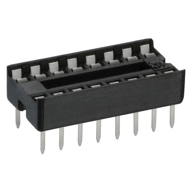
Along with the suggestions for the board, you can also get IC sockets that will let you plug in the chip after you're all done wiring.
You can solder in the socket without worrying about damaging the chip.
If you ever find a need to replace the chip, you'll be happy you can just pull it out and simply plug in the new one-
Something like this is 18 cents from digikey-
decifer diagram? - Page 3 -- posted image.
hotwaterwizard 
Silver - Posts: 1,350
Silver spacespace
Joined: December 11, 2003
Location: California, United States
Posted: November 30, 2008 at 11:34 AM / IP Logged  

http://www.radioshack.com/product/index.jsp?productid=2062607

decifer diagram? - Page 3 -- posted image.

Radio Shack no shipping no waiting.
John DeRosa (Hotwaterwizard)
Stockton California
When in doubt, try it out !
blkrhyno 
Copper - Posts: 71
Copper spacespace
Joined: August 16, 2008
Location: New York, United States
Posted: November 30, 2008 at 4:30 PM / IP Logged  

Thanks, you guys are extremely helpful. I have another stupid question, do I wire the diodes, resistors & caps on the wire or on the board? Is it at all possible for one of you guys to draw a diagram showing how it should be wired on the board?

Protect what's yours.
dualsport 
Silver - Posts: 983
Silver spacespace
Joined: September 27, 2005
Location: United States
Posted: December 01, 2008 at 11:04 PM / IP Logged  
You should be able to put all the components on the board. You know how to use a soldering iron, I assume- If you print out the schematic you can just use a highlighter to mark off the connections you've made, and just go until you have everything connected. That'll help you keep track of what else you have to connect together as you go.
Use sockets for the IC and transistors, the other stuff you should be able to solder on directly, as they're more rugged.
If you anticipate needing to modify the timing, you can use sockets for the resistor and cap to be able to easily change them by plugging in new values.
blkrhyno 
Copper - Posts: 71
Copper spacespace
Joined: August 16, 2008
Location: New York, United States
Posted: December 02, 2008 at 5:27 PM / IP Logged  
Yes I know how to use a soldering iron, thank you for all your help, I'll let you know how it works out.
Protect what's yours.
blkrhyno 
Copper - Posts: 71
Copper spacespace
Joined: August 16, 2008
Location: New York, United States
Posted: December 02, 2008 at 7:01 PM / IP Logged  
Sorry one more question, do I run wires from the board to the relays? In other words, how do i connect the curcuit board to the relays?
Protect what's yours.
dualsport 
Silver - Posts: 983
Silver spacespace
Joined: September 27, 2005
Location: United States
Posted: December 02, 2008 at 7:39 PM / IP Logged  
I assume you're not going to use any board mount type relays, but the standard automotive types with the blade connectors, so you'll be connecting wires to the board-
Get one of the commonly available relay socket harnesses, and you can connect the wires from the harness to the board and plug the relays into the harness sockets.
Page of 5

  Printable version Printable version Post ReplyPost New Topic
You cannot post new topics in this forum
You cannot reply to topics in this forum
You cannot delete your posts in this forum
You cannot edit your posts in this forum
You cannot create polls in this forum
You cannot vote in polls in this forum

  •  
Search the12volt.com
Follow the12volt.com Follow the12volt.com on Facebook
Saturday, May 4, 2024 • Copyright © 1999-2024 the12volt.com, All Rights Reserved Privacy Policy & Use of Cookies
Disclaimer: *All information on this site ( the12volt.com ) is provided "as is" without any warranty of any kind, either expressed or implied, including but not limited to fitness for a particular use. Any user assumes the entire risk as to the accuracy and use of this information. Please verify all wire colors and diagrams before applying any information.

Secured by Sectigo
the12volt.com spacer
Support the12volt.com
Top
the12volt.com spacer