the12volt.com spacer
icon

2009 Honda CR-V Remote Start And Wiring


Post ReplyPost New Topic
< Prev Topic Next Topic >
cpgoose 
Gold - Posts: 1,098
Gold spacespace
Joined: July 08, 2002
Location: United States
Posted: February 20, 2009 at 6:31 AM / IP Logged  
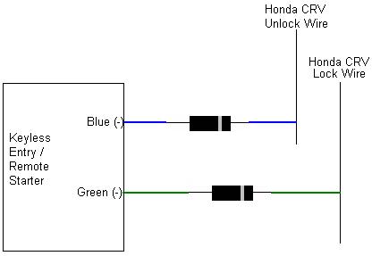
Cool, thanks loneranger. Since it's been a while that I've used diodes, let me just confirm that I will hook it up correctly:
2009 Honda CR-V Remote Start And Wiring - Page 3 -- posted image.
loneranger 
Copper - Posts: 572
Copper spacespace
Joined: December 28, 2008
Posted: February 20, 2009 at 1:20 PM / IP Logged  

Flip your diodes around. They are backwards.

Ideal - cmon dude, add to topics in a useful manner, not stuff that is obvious.
Story - Phzzzt! Hey, what happened?! ... Isn't it obvious?
Moral - Never dismiss the obvious.
cpgoose 
Gold - Posts: 1,098
Gold spacespace
Joined: July 08, 2002
Location: United States
Posted: February 20, 2009 at 1:24 PM / IP Logged  
Crap...I always get that backwards. So by flipping them around it makes it so that the 1400xp can only send the negative pulse TO the unlock and lock wires, right? It prevents signal going TO the 1400xp?
loneranger 
Copper - Posts: 572
Copper spacespace
Joined: December 28, 2008
Posted: February 20, 2009 at 2:56 PM / IP Logged  
Your concept is correct. DEI, as well as other designs, uses a flip-flop circuit for the outputs. If the factory switch in the vehicle is inadvertently locking, at the same time the flip-flop circuit is unlocking, the module could be severely damaged; or visa-versa. The diodes prevent the positive voltage from grounding, through the factory lock/unlock switches.
Ideal - cmon dude, add to topics in a useful manner, not stuff that is obvious.
Story - Phzzzt! Hey, what happened?! ... Isn't it obvious?
Moral - Never dismiss the obvious.
howie ll 
Pot Metal - Posts: 16,466
Pot Metal spacespace
Joined: January 09, 2007
Location: United Kingdom
Posted: February 20, 2009 at 3:21 PM / IP Logged  
We had  loads of iritations with DEI/Clifford early G5 product with those flip flop driven lock outputs, I got to "conditioning" every install!  Thanfully they listened to our complaints and made them relay driven last year.
loneranger 
Copper - Posts: 572
Copper spacespace
Joined: December 28, 2008
Posted: February 20, 2009 at 3:39 PM / IP Logged  

DEI is no longer using a trasistorized circuit, for the lock/unlock outputs on 2-wire models? Which models are you speaking of? I haven't seen any on-board relays yet, much less 5-wire outputs. Maybe they mis-informed you and they are using current-limiting instead, or I could be completely off base.

Ideal - cmon dude, add to topics in a useful manner, not stuff that is obvious.
Story - Phzzzt! Hey, what happened?! ... Isn't it obvious?
Moral - Never dismiss the obvious.
howie ll 
Pot Metal - Posts: 16,466
Pot Metal spacespace
Joined: January 09, 2007
Location: United Kingdom
Posted: February 20, 2009 at 4:22 PM / IP Logged  
The Euro Cat G5 AKA Concept 650 was based on the Concept 550 with various upgrades to turn it into a UK Cat1*. The siren becomes battery back up, the CPU gets an armoured case which must be bolted/screwed or cable tied home, dual circuit passive immobilisers, all immob and power and ground lines black, mandatory hood, trunk and door contacts.  And of course stealth wiring, solder joints etc.  We had loads of complaints centred around the lock outputs, high sensitivity to sleep circuits, and the Wiz V2.2 was a nightmare when adding Intellistart. They modded it 18months ago, to the Concept 650 Mk ll with the new silver remotes, effectively an Intelliguard 850 modded as above. Now it has relay driven outputs, a total (comfort close) option and it's step sister Viper 500XV is similar except for two way remote. Just a point for your clarification, the rest of the world outside North America uses amber indicators front and back, thus we don't wire to the lights, we wire to the indicators or hazards.  *UK Cat l is recognised everywhere but Australia/NZ. They require 3 cut . The insurers started Cat l, especially for fast and furious type Japapnese imports, without transponders etc.  The (irritating) passive immobilisation is thanks to German TUV.
loneranger 
Copper - Posts: 572
Copper spacespace
Joined: December 28, 2008
Posted: February 21, 2009 at 3:39 PM / IP Logged  
Wow! Thanks for schoolin' me!
Ideal - cmon dude, add to topics in a useful manner, not stuff that is obvious.
Story - Phzzzt! Hey, what happened?! ... Isn't it obvious?
Moral - Never dismiss the obvious.
cpgoose 
Gold - Posts: 1,098
Gold spacespace
Joined: July 08, 2002
Location: United States
Posted: March 17, 2009 at 8:46 PM / IP Logged  
Hey guys...hopefully you're still subscribed to this post...I just had a few questions now that I'm almost done.
1. I'm trying to figure out whether the Python brain in setup for + or - output for the doorlocks. I see that it can do both, but I'm not sure which one it's set to at the moment. Do you know how to check? I never understand how to check with a DMM since I'll get one signal with the 2 wires going one way, and I'll get the opposite (-) signal if I swap them.
2. I found a blue/white wire next to the ECM that I'm assuming in the tach wire. Actually I found 2. One doesn't respond at all to the RPMs, and the other one shoots up very briefly with the RPMs, and then falls back down. I couldn't really get it to hover between 1 and 6v, but I think it's probably the wire.
3. As I've seen in a lot of other posts, the door lock spot refers to the TechTip 1041, but I don't have access. Does that have anything that I'd need to know?
Thanks!~
chriswallace187 
Gold - Posts: 1,661
Gold spacespace
Joined: March 11, 2002
Location: Pennsylvania, United States
Posted: March 17, 2009 at 9:17 PM / IP Logged  
cpgoose wrote:
Hey guys...hopefully you're still subscribed to this post...I just had a few questions now that I'm almost done.
1. I'm trying to figure out whether the Python brain in setup for + or - output for the doorlocks. I see that it can do both, but I'm not sure which one it's set to at the moment. Do you know how to check? I never understand how to check with a DMM since I'll get one signal with the 2 wires going one way, and I'll get the opposite (-) signal if I swap them.
This isn't a programmable option. When "lock" is pressed on the remote the green wire will output a (-) pulse and the blue will output (+). When "unlock" is pressed the opposite will happen. Most cars with positive or negative 3-wire door lock systems can be directly connected to these wires and the (in your case) positive pulse will have no effect since the wires rest at 12V+ through the factory relays/lock controller.
cpgoose wrote:
2. I found a blue/white wire next to the ECM that I'm assuming in the tach wire. Actually I found 2. One doesn't respond at all to the RPMs, and the other one shoots up very briefly with the RPMs, and then falls back down. I couldn't really get it to hover between 1 and 6v, but I think it's probably the wire.
You could try "tach-find-by-fire", if you don't mind the name I've just coined for it. Connect the violet/white from the Python temporarily to the suspected tach wire, and attempt to program it to the Python. If the LED never comes on, it won't work. If the LED lights up, it's probably good and you can attempt a remote start to verify that the cranking time is sufficient and not excessive.
cpgoose wrote:
3. As I've seen in a lot of other posts, the door lock spot refers to the TechTip 1041, but I don't have access. Does that have anything that I'd need to know?
Thanks!~
1041 is in the Downloads section of this site. Look at it if you like - it's simply a guide to the different types of lock systems.
C Renner's Auto Electronix
My service is cheap, quick, and good - pick any two
Page of 5

  Printable version Printable version Post ReplyPost New Topic
You cannot post new topics in this forum
You cannot reply to topics in this forum
You cannot delete your posts in this forum
You cannot edit your posts in this forum
You cannot create polls in this forum
You cannot vote in polls in this forum

  •  
Search the12volt.com
Follow the12volt.com Follow the12volt.com on Facebook
Monday, May 12, 2025 • Copyright © 1999-2025 the12volt.com, All Rights Reserved Privacy Policy & Use of Cookies
Disclaimer: *All information on this site ( the12volt.com ) is provided "as is" without any warranty of any kind, either expressed or implied, including but not limited to fitness for a particular use. Any user assumes the entire risk as to the accuracy and use of this information. Please verify all wire colors and diagrams before applying any information.

Secured by Sectigo
the12volt.com spacer
Support the12volt.com
Top
the12volt.com spacer