the12volt.com spacer
icon

keyless entry issue for 93 rx7


Post ReplyPost New Topic
< Prev Topic Next Topic >
lanman31337 
Copper - Posts: 83
Copper spacespace
Joined: August 11, 2005
Posted: January 29, 2009 at 6:26 AM / IP Logged  
I'm with Chris - it looks like you can pulse the 0 (i'm guessing orange) wire from the actuator with a negative pulse and it should unlock. Also the G (Green?) from the lock with a negative pulse and it would work as well.
ckeeler 
Gold - Posts: 1,461
Gold spacespace
Joined: June 20, 2008
Location: New Mexico, United States
Posted: January 29, 2009 at 8:16 AM / IP Logged  

and actually rotorypower, dont let me mislead you. you will need 2 of these relays. you will have to use another relay like the one i showed you to "break" the "B" wire and hold it open in an armed (on lock state) until you unlock closing the "B" wire, allowing the switch to function as normal. the reason being is you cant just use the one relay because what if the switch is resting between "B" and "G/R", and your relay pulses "B" to "G/Y"? so you must you another relay to disconnect "B" from the switch when arming and hold it there while armed so you can trigger the wires form "B" through the other relay. on disarm it would connect "B" back together so you could use the switch as normal. second relay diagram is below.

keyless entry issue for 93 rx7 - Page 2 -- posted image.

rotarypower101 
Member - Posts: 19
Member spacespace
Joined: July 27, 2006
Posted: January 29, 2009 at 5:54 PM / IP Logged  
OK I think i see where you are going with this now, I will not have time to sufficiently go over the details and see if it will work until Saturday though.
Are you suggesting removing the switch and replacing it with a controllable DPDT relay and this is where the signal from the keyless entry is coming from?
If this is you suggestion I am not sure it will work, because the switch in the diagram is an integral part of the system as it is there to tell all the doors to unlock when a user manually pulls the locking mechanism in the car.
Removing this “door lock switch” would sacrifice one feature in lieu of another.
However I may be able to piggyback the system without issue, which you might also be suggesting? Y/N?
rotarypower101 
Member - Posts: 19
Member spacespace
Joined: July 27, 2006
Posted: January 29, 2009 at 5:54 PM / IP Logged  
BTW ckeeler thanks for the help and ideas, I really would like to make this work properly, and am stuck until a solution presents itself to be able to finish the rest of my little project.
Also, can you describe in your most elaborate descriptive explanation how this DPTH relay will work if the coil polarity is not toggled upon activation or a push of the momentary switch?
That was the issue I could never overcome.
rotarypower101 
Member - Posts: 19
Member spacespace
Joined: July 27, 2006
Posted: January 29, 2009 at 6:01 PM / IP Logged  
Sorry for the above posts they were in regards to yesterdays postings, as I had not refreshed the page to see the newer current posts.
ckeeler 
Gold - Posts: 1,461
Gold spacespace
Joined: June 20, 2008
Location: New Mexico, United States
Posted: January 29, 2009 at 6:27 PM / IP Logged  

rotarypower101 wrote:
   I may be able to piggyback the system without issue, which you might also be suggesting? Y/N?

Yes thats what i mean. is it making sense now? with the diagrams and all?

rotarypower101 
Member - Posts: 19
Member spacespace
Joined: July 27, 2006
Posted: January 29, 2009 at 10:02 PM / IP Logged  
I am fairly certain there is no way to simply pulse the actuator, as it is not a solenoid, but a motor that turns axially and twits a matting “finger” that locks/unlocks the latching mechanism.
chriswallace187 wrote:
Is there a possibility that the diagram is just wrong as far as the switch(specifically, should it show the lock switch as normally open entirely rather than normally closed with the GREEN/ red unlock)? And that simply connecting the (-) outputs from an aftermarket keyless entry would work the locks properly?
rotarypower101 
Member - Posts: 19
Member spacespace
Joined: July 27, 2006
Posted: January 29, 2009 at 10:18 PM / IP Logged  
Hey ckeeler, ya I think what you are saying will probably work, I am going to try and throw something together tonight and see if I cant make it work. Luckily I have some unused latching relays gathering dust from july 06 that just might fit the bill ;)
ckeeler 
Gold - Posts: 1,461
Gold spacespace
Joined: June 20, 2008
Location: New Mexico, United States
Posted: January 29, 2009 at 11:45 PM / IP Logged  
ha! yea you probably do huh? in any case i know it will work im certain of it. if you need i can draw up the diagram with both relays and the wires in the car to make it more clear, but you seem like you know the system in this car very well, and i think you get what im showing you (at least i hope so). the switch will still work as normal with this setup and you still be able to do the keyless entry as well. so you'll be good.
chriswallace187 
Gold - Posts: 1,661
Gold spacespace
Joined: March 11, 2002
Location: Pennsylvania, United States
Posted: January 29, 2009 at 11:55 PM / IP Logged  
rotarypower101 wrote:
I am fairly certain there is no way to simply pulse the actuator, as it is not a solenoid, but a motor that turns axially and twits a matting “finger” that locks/unlocks the latching mechanism.
I know you wouldn't pulse the motor wires, but the switched wires from the manual motion of the actuator should do the trick. Since you've already presumably got it working so that moving either actuator will operate both doors, I think if you send a ground to the respective "lock" and "unlock" switch wires, both doors will operate as you want them to.
The lock timer with its capacitors and such is basically a non-issue. Its purpose is roughly the same as the constant-to-momentary relay that the12volt has shown here:
keyless entry issue for 93 rx7 - Page 2 -- posted image.
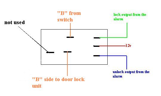
The factory lock circuit on your RX-7 is more or less the same design. When the actuator is moved to the Locked or Unlocked position, it grounds the GREEN/ YELLOW or GREEN/ Red wire respectively. This in turn activates the respective relay which is integrated into the timer module (you can see the coils and the switching contacts of each relay connected by the dashed line). This is a very common method of switching used by central locking systems(those controlled by movement of the lock itself rather than a separate switch).
Since the grounded GREEN/ YELLOW or GREEN/ Red is connected directly to the relay coil the path of least resistance would be the coil itself, which would send power to the actuator constantly. This is the reason for the capacitors - once they charge(after 0.5-1.0 seconds) the relay cuts out and the actuator stops trying to move any further.
Try applying ground yourself to the GREEN/ YELLOW and GREEN/ Red, and I'm extremely confident it will operate the doorlocks as you want it to without the need for extra relays.
chriswallace187 wrote:
Is there a possibility that the diagram is just wrong as far as the switch(specifically, should it show the lock switch as normally open entirely rather than normally closed with the GREEN/ red unlock)? And that simply connecting the (-) outputs from an aftermarket keyless entry would work the locks properly?
C Renner's Auto Electronix
My service is cheap, quick, and good - pick any two
Page of 3

  Printable version Printable version Post ReplyPost New Topic
You cannot post new topics in this forum
You cannot reply to topics in this forum
You cannot delete your posts in this forum
You cannot edit your posts in this forum
You cannot create polls in this forum
You cannot vote in polls in this forum

  •  
Search the12volt.com
Follow the12volt.com Follow the12volt.com on Facebook
Wednesday, April 24, 2024 • Copyright © 1999-2024 the12volt.com, All Rights Reserved Privacy Policy & Use of Cookies
Disclaimer: *All information on this site ( the12volt.com ) is provided "as is" without any warranty of any kind, either expressed or implied, including but not limited to fitness for a particular use. Any user assumes the entire risk as to the accuracy and use of this information. Please verify all wire colors and diagrams before applying any information.

Secured by Sectigo
the12volt.com spacer
Support the12volt.com
Top
the12volt.com spacer