the12volt.com spacer
icon

pg octane 900.5 repair


Post ReplyPost New Topic
< Prev Topic Next Topic >
ianarian 
Copper - Posts: 516
Copper spacespace
Joined: April 24, 2009
Location: California, United States
Posted: June 27, 2009 at 6:32 AM / IP Logged  
My brother crossed polarity on the power and ground terminals of this amp. The 40a fuse for sub obviously smoked. Both 25a fuses for Front and Rear are fine. The amp still plays fine as a 4ch. The 5ch smokes fuses though. I gave him a new amp but was wondering if there is something we can do to get the sub line working again.
This is what I do for FUN!
i am an idiot 
Platinum - Posts: 13,667
Platinum spaceThis member consistently provides reliable informationspace
Joined: September 21, 2006
Location: Louisiana, United States
Posted: June 27, 2009 at 3:28 PM / IP Logged  

If the amp was properly fused, there should have not been any damage.  If you have an Ohm meter and a digital camera,  And can answer some questions, I am sure we can figure out what the problem is.

If polarity was reversed, it would have blown all of the fuses. 

Let's Go Brandon Brown. Congratulations on your first Xfinity Series Win. LGBFJB
ianarian 
Copper - Posts: 516
Copper spacespace
Joined: April 24, 2009
Location: California, United States
Posted: June 28, 2009 at 3:27 AM / IP Logged  
To the best of his recollection only the 40a blew.(comming from the guy who reversed wires in the 1st place) Uh huh, anyway I got the meter but I think I need to get ya a clearer pic. pg octane 900.5 repair -- posted image.
This is what I do for FUN!
i am an idiot 
Platinum - Posts: 13,667
Platinum spaceThis member consistently provides reliable informationspace
Joined: September 21, 2006
Location: Louisiana, United States
Posted: June 28, 2009 at 7:45 AM / IP Logged  
That picture will do for now.  Place a 10 amp fuse in the slot that is blowing.   I need you to connect only the power wire and the ground wire.  Do not connect the remote wire.  Does the fuse blow with only power and ground connected?
i am an idiot 
Platinum - Posts: 13,667
Platinum spaceThis member consistently provides reliable informationspace
Joined: September 21, 2006
Location: Louisiana, United States
Posted: June 28, 2009 at 8:20 AM / IP Logged  

Do not remove the clamps from the heat sink unless we determine it is necessary.  The cleanliness of the bond of the transistors to the heat sink is important.  The less time it spends apart the better off we are.

If it blows the fuse without the remote terminal connected, the problem lies in the power supply area.  If it only blows the fuse when remote power is applied, the problem lies in the output devices.   Look for the large diode to the left of the picture.  There may or may not be one. 

pg octane 900.5 repair -- posted image.

ianarian 
Copper - Posts: 516
Copper spacespace
Joined: April 24, 2009
Location: California, United States
Posted: June 29, 2009 at 1:29 AM / IP Logged  
It blew a 10a without the remote hooked up. I dont see a diode that stands out as large. There is one that I would consider the larger than the rest though.
This is what I do for FUN!
i am an idiot 
Platinum - Posts: 13,667
Platinum spaceThis member consistently provides reliable informationspace
Joined: September 21, 2006
Location: Louisiana, United States
Posted: June 29, 2009 at 6:01 AM / IP Logged  

With your meter set to the diode test function, it should be the only setting with a symbol.  It is the symbol for a diode.  pg octane 900.5 repair -- posted image.

Remove all fuses from the amp, There are 3 legs on each of the power supply transistors.  Place and hold one meter lead to the center leg of the first transistor, now touch the other lead to another leg of the same transistor.  Write down that reading.  Now move the last lead to the other leg ot the transistor.  Write down that reading.  Move to the next transistor.  Repeat.  On either the set of 4 or the set of 6 there will be one or more of them that read very near 0.00  This is the problem set of transistors.  Once you figure out the shorted set, remove the clamp from that set of transistors so we can get the number off of the top of the transistor.   If you can not read the numbers, place your finger in some of the white heat sink grease and rub it onto the top of the transistor.  Wipe most of it off and you will be able to read the number.

ianarian 
Copper - Posts: 516
Copper spacespace
Joined: April 24, 2009
Location: California, United States
Posted: June 29, 2009 at 8:50 PM / IP Logged  
pg octane 900.5 repair -- posted image.
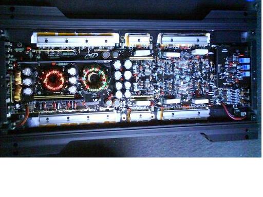
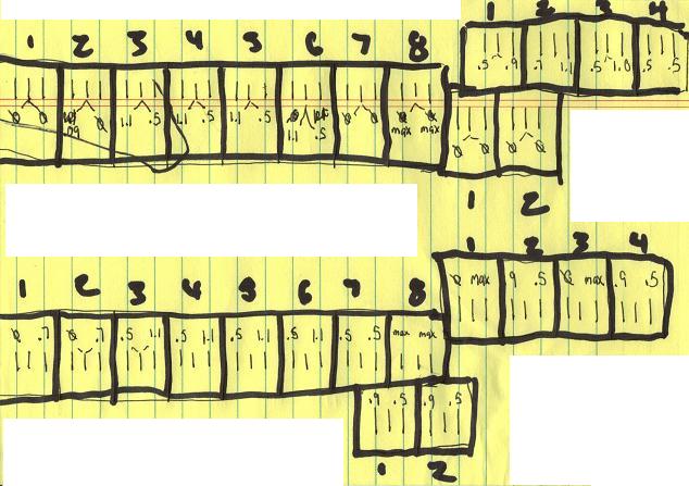
Hope this makes sense but its arranged just as we see the amp in the other pick. I metered every transistor under the heat sinks. Some say max because the meter kept going up until 2.0 where it went to open circuit. 0 obviously didnt get a reading. Looks as if every heat sink but 2 has a bad transistor under it. I'll grab those #'s for ya too.
This is what I do for FUN!
i am an idiot 
Platinum - Posts: 13,667
Platinum spaceThis member consistently provides reliable informationspace
Joined: September 21, 2006
Location: Louisiana, United States
Posted: June 29, 2009 at 9:02 PM / IP Logged  
pg octane 900.5 repair -- posted image.
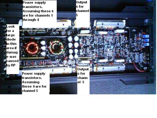
It appears as though the amp has shorted output transistors. There is no way connecting the amp backwards shorted these components. The output transistors shorted and in turn took out the power supply.
With your meter set to the diode test function, what does it read when you hold the leads together?
The transistor on the top left of the picture is definitely shorted. I am 99% sure the ones at top right of this picture are shorted. I need the info about your meter to be sure.
ianarian 
Copper - Posts: 516
Copper spacespace
Joined: April 24, 2009
Location: California, United States
Posted: June 30, 2009 at 3:10 AM / IP Logged  
All four transistors are labeled DFP50N06/4206.
The other 2 separate transistors cycle to .OL, when the common lead is on the transistor side and the red lead is on either +/- sub terminal.(SWITCHING LEADS) If the common lead is on the sub side then im getting .903 across both transistors mid leg to sub(+), and .491 from both transistors mid leg to sub(-). Transistor #1 labeled-TIP36C/() 638. Transistor #2 labeled-TIP36C/ () 636.
My meter is a Wavetek Meterman...it reads .000 at lead tips.
My brother is a journey inside wireman and admitted the reversing mistake. Which must of been hard to do. He knows what he's doin by all means. Hmmmm something fishy goin on here!
This is what I do for FUN!
Page of 8

  Printable version Printable version Post ReplyPost New Topic
You cannot post new topics in this forum
You cannot reply to topics in this forum
You cannot delete your posts in this forum
You cannot edit your posts in this forum
You cannot create polls in this forum
You cannot vote in polls in this forum

  •  
Search the12volt.com
Follow the12volt.com Follow the12volt.com on Facebook
Wednesday, April 17, 2024 • Copyright © 1999-2024 the12volt.com, All Rights Reserved Privacy Policy & Use of Cookies
Disclaimer: *All information on this site ( the12volt.com ) is provided "as is" without any warranty of any kind, either expressed or implied, including but not limited to fitness for a particular use. Any user assumes the entire risk as to the accuracy and use of this information. Please verify all wire colors and diagrams before applying any information.

Secured by Sectigo
the12volt.com spacer
Support the12volt.com
Top
the12volt.com spacer