the12volt.com spacer
icon

pg octane 900.5 repair


Post ReplyPost New Topic
< Prev Topic Next Topic >
i am an idiot 
Platinum - Posts: 13,667
Platinum spaceThis member consistently provides reliable informationspace
Joined: September 21, 2006
Location: Louisiana, United States
Posted: June 30, 2009 at 5:33 AM / IP Logged  

We need to cut the legs off of the top left transistor and both of the TIP 36 transistors.   Cut the legs off as close as you can to the case of the transistor.  After cutting each leg, move it a bit towards the center of the board to make sure it is not making contact with the transistor.  REPLACE ALL of the clamps that you removed, Place a 10 amp fuse in the slot that has been blowing.  And if you have (2) 5 amp fuses, place them in the other 2 slots.   Place the amp back in the vehicle and connect power ground and remote.  It may or may not blow the 10 amp fuse, if it does not blow the fuse,

Set your meter to the DC Volts selection.  I need to know the DC voltage from the outside legs of the 4 power supply transistors.  2 on top of pic and 2 on bottom of pic.  These are the only 4 parts that we are concerned about at this time.

ianarian 
Copper - Posts: 516
Copper spacespace
Joined: April 24, 2009
Location: California, United States
Posted: June 30, 2009 at 7:00 PM / IP Logged  
For now I got the amp on my bench its covered and clean and well lit. The 10a sub fuse blew as soon as I switched on remote.
This is what I do for FUN!
i am an idiot 
Platinum - Posts: 13,667
Platinum spaceThis member consistently provides reliable informationspace
Joined: September 21, 2006
Location: Louisiana, United States
Posted: June 30, 2009 at 7:11 PM / IP Logged  
How many transistors did you cut out of the circuit?
ianarian 
Copper - Posts: 516
Copper spacespace
Joined: April 24, 2009
Location: California, United States
Posted: June 30, 2009 at 7:32 PM / IP Logged  
3 total
This is what I do for FUN!
i am an idiot 
Platinum - Posts: 13,667
Platinum spaceThis member consistently provides reliable informationspace
Joined: September 21, 2006
Location: Louisiana, United States
Posted: June 30, 2009 at 8:22 PM / IP Logged  

Check the transistors directly across from the TIP36Cs.  They should be TIP35Cs.  Also check these from the left leg to the right leg.  Also recheck the one remaining transistor at the top left of the pic, and the 2 at the bottom left of the picture.

Also there is a resistor connected to the left leg of each of the power supply transistors.  The transistors in the top row of the pic are positioned correctly.  The bottom row are positioned opposite.  The resistor will be connected to the left leg of the top row and the right leg of the bottom row.  Using the meter now set to the Ohms selection, what is the reading of the 4 transistors we are checking now?  Is the resistor that was connected to the top left discolored or burnt?

ianarian 
Copper - Posts: 516
Copper spacespace
Joined: April 24, 2009
Location: California, United States
Posted: July 01, 2009 at 12:32 AM / IP Logged  
Yes they are tip35's, lookin at the face/label the 3 legs commming down, are they B,C,E in that order? Lets say that the (Center to Left) legs-.551 on both tip35's. (Center to Right) leg is .OL on both tip35's
the one remaining transistor at the top left of the pic-1.13(C-L) .460(C-R)
and the 2 at the bottom left of the picture.(C-L)1.130 (C-R).458 same for both
I didnt get a ohm reading on the four transistors, testing them in the same fashion as the diode tests.C-L,C-R
All the resistors look ok/same too.
This is what I do for FUN!
i am an idiot 
Platinum - Posts: 13,667
Platinum spaceThis member consistently provides reliable informationspace
Joined: September 21, 2006
Location: Louisiana, United States
Posted: July 01, 2009 at 5:21 AM / IP Logged  
Cut out the other transistor top left of your diagram.  Try the fuse again.  We may have a problem with the driver transistor that drives the 2 top transistors.  I need to know the value of the resistors, and also follow the trace from the other end of the resistor.  It will go to a small transistor.  It may go to 2 transistors.  I need the number on both of those transistors.
ianarian 
Copper - Posts: 516
Copper spacespace
Joined: April 24, 2009
Location: California, United States
Posted: July 01, 2009 at 4:38 PM / IP Logged  
Ok, she blew a 10a when remote switched on..
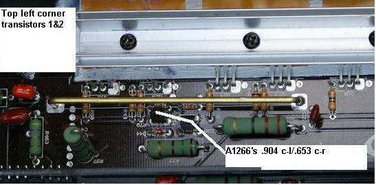
our two little transistors are both labeled K/620/A1266/Y
the resistors are yellow, purple, black, gold they metered to 46.2ohm
i am an idiot 
Platinum - Posts: 13,667
Platinum spaceThis member consistently provides reliable informationspace
Joined: September 21, 2006
Location: Louisiana, United States
Posted: July 01, 2009 at 6:44 PM / IP Logged  

The A1266s  I am assuming that one is connected to the resistors in top of pic and the other is connected to resistors in the bottom of the pic.  With your meter I need ot make sure both of these give the same readings as the other one.  Check all possible combinations of leg and lead positions. 

Also check the 35s from left leg to right leg. 

ianarian 
Copper - Posts: 516
Copper spacespace
Joined: April 24, 2009
Location: California, United States
Posted: July 01, 2009 at 10:58 PM / IP Logged  
There is no continuity across the L and R legs of the 35's. I located 4 total mini transistors all appearing to be branched of the resistor as we discussed which all have the same reading. center-Leg1 .904 / center-leg2 .653. Reading displays promptly and stable.
pg octane 900.5 repair - Page 2 -- posted image.
This is what I do for FUN!
Page of 8

  Printable version Printable version Post ReplyPost New Topic
You cannot post new topics in this forum
You cannot reply to topics in this forum
You cannot delete your posts in this forum
You cannot edit your posts in this forum
You cannot create polls in this forum
You cannot vote in polls in this forum

  •  
Search the12volt.com
Follow the12volt.com Follow the12volt.com on Facebook
Friday, April 19, 2024 • Copyright © 1999-2024 the12volt.com, All Rights Reserved Privacy Policy & Use of Cookies
Disclaimer: *All information on this site ( the12volt.com ) is provided "as is" without any warranty of any kind, either expressed or implied, including but not limited to fitness for a particular use. Any user assumes the entire risk as to the accuracy and use of this information. Please verify all wire colors and diagrams before applying any information.

Secured by Sectigo
the12volt.com spacer
Support the12volt.com
Top
the12volt.com spacer