the12volt.com spacer
icon

2010 ford fusion, viper 5901


Post ReplyPost New Topic
< Prev Topic Next Topic >
tedmond 
Gold - Posts: 4,610
Gold spaceThis member has been recognized as an authority in Mobile Security and Convenience. Click here for more info.spacespace
Joined: January 06, 2007
Location: Ontario, Canada
Posted: February 18, 2010 at 7:07 AM / IP Logged  

just a tip, you might find it easier if you have a piece of wire comming off the other end as well.

I dont know if you are soldering the diode to the wire on the van or the wire part goes to the van, WHen you have wire branching off the diode from both ends, it makes it easier for a more clean/factory look.

when adding additional sensors, you will need to isolate them. I am not too familiar with the new DEI brains, but from what i remember the shock sensor is built in, andif addition sensors want to be added, its simply plug into the existing socket on the brain.

also, i would like to thank you for being patient and taking this install on to learn something, and you actaully READ what we got to say. Had my fair share of stubborn people.

 Cheers

Ted
2nd Year Tier 1 Medical School
Still installing as a hobby...pays for groceries
Compustar Expert
monty862 
Copper - Posts: 116
Copper spaceThis member has made a donation to the12volt.com. Click here for more info.spacespace
Joined: December 10, 2009
Location: Kentucky, United States
Posted: February 18, 2010 at 8:09 AM / IP Logged  

That's one of the great things about these forums, you get the input of so many people. If you get an opposing opinion on something then you have a chance to see it from another perspective. I appreciate you and everyone taking the time to read and post what they think is the best or correct answer. As for the diodes, the wired side is going to the smart junction box. It is a pain in the a** to get at. After I see how long I need the leads from the diodes to be, then I'll solder the other end on before attaching to the SJB wires. I was going to bring these diodes down to the kick panel area in case they ever fail. Don't want to have to get back to this SJB again. I was hoping to avoid going to the SJB altogether, but it is the only place my install sheet lists for location of the door trigger wires. I asked on an earlier post if I could connect my parking lights at the headlight switch, but they didn't recommend it. Since I have to go to the SJB for the door triggers, it's not that much more bother. On the subject of the 5901, it has a single "mux" input for an add-on sensor. I plan on using it for a proximity (radar) sensor.  I believe for additional instant trigger inputs you are suppose to use the blue H1 trunk trigger wire. I also purchased a tilt and external shock sensor in case the internal sensor wasn't sensitive enough. Hopefully I won't need the external sensor. Thanks again!

monty862 
Copper - Posts: 116
Copper spaceThis member has made a donation to the12volt.com. Click here for more info.spacespace
Joined: December 10, 2009
Location: Kentucky, United States
Posted: February 25, 2010 at 6:42 AM / IP Logged  
I got my door triggers wired up. My install sheet stated (N.C. negative). I installed the diodes with the bands towards the SJB. Connected the other ends to the green H1/8 wire. When testing the alarm, I get no response when I open any door. The message center on the car is still functioning properly and will tell which door is open. I found a conflicting install sheet from Installogy that stated (N.O. negative). I changed the setting on the 5901 to N.O. and then when arming it reports door open when they are not. Any ideas on where I went wrong? Thanks
monty862 
Copper - Posts: 116
Copper spaceThis member has made a donation to the12volt.com. Click here for more info.spacespace
Joined: December 10, 2009
Location: Kentucky, United States
Posted: February 25, 2010 at 12:02 PM / IP Logged  

I tested each lead after I attached them to the door trigger wires. The DMM showed a limited continuity reading to ground when the door was closed, and no reaction when the door was open. Thought this sounded right. Trunk trigger works fine. So does the hood trigger. Anyone see this before? Thanks

monty862 
Copper - Posts: 116
Copper spaceThis member has made a donation to the12volt.com. Click here for more info.spacespace
Joined: December 10, 2009
Location: Kentucky, United States
Posted: February 26, 2010 at 8:01 AM / IP Logged  
I found this possible solution online. Do you think it applies to my situation?            "The small pulse is not strong enough to trigger the alarm. Diode isolate each door trigger and wire to a relay.  When the door opens it will trigger the relay and send a ground to the alarm. How to? Combine all diode isolated trigger wires and connect that wire to pin 85 and 12V to pin 86. Then pin 87 to ground and pin 30 to the alarm."               Thanks 
monty862 
Copper - Posts: 116
Copper spaceThis member has made a donation to the12volt.com. Click here for more info.spacespace
Joined: December 10, 2009
Location: Kentucky, United States
Posted: February 27, 2010 at 3:35 PM / IP Logged  
This didn't work. Any suggestions appreciated.
monty862 
Copper - Posts: 116
Copper spaceThis member has made a donation to the12volt.com. Click here for more info.spacespace
Joined: December 10, 2009
Location: Kentucky, United States
Posted: March 14, 2010 at 5:27 AM / IP Logged  
Update on 2010 Fusion door triggers. It looks like a module called a DTIMAZDA (Door Trigger Interface- Mazda, because I guess it was the first automaker to need it) is required. It changes the system from a Negative Normally Closed, to Positive Normally Open. It has 10 connections that are required. You cut all four of the cars door trigger wires. Four of the DTIMAZDA wires go to one side of the cut wires and four go to the other side of the cut wires. One goes to 12 volts and the last to the positive door trigger wire on the 5901. Once this was installed and the settings on the 5901 were adjusted the alarm functions properly. Thanks to Howie for the info. More install pics soon.
monty862 
Copper - Posts: 116
Copper spaceThis member has made a donation to the12volt.com. Click here for more info.spacespace
Joined: December 10, 2009
Location: Kentucky, United States
Posted: March 18, 2010 at 8:06 AM / IP Logged  
Here are a couple of more installation pics. The majority of the alarm connections can be made from the headlight / message center / trunk pop/ switch pod. The two connectors shown unplug from the smart junction box and all their wires will extend out through the switch pod location. The small 26 pin connector (c) has the four door triggers, trunk trigger, trunk pop, power locks, parking brake and hood pin. Talk about convenient. It also lists, trunk alarm shunt. Not sure what that does, I'll have to ask Howie. The larger connector (d) has the parking lights. 2010 ford fusion, viper 5901 - Page 4 -- posted image.  Here is the field disturbance sensor. I was able to mount it in the console under the storage bin. This rectangular cut out in the bottom of the bin, under the liner, allows access to adjustment screws. 2010 ford fusion, viper 5901 - Page 4 -- posted image.
monty862 
Copper - Posts: 116
Copper spaceThis member has made a donation to the12volt.com. Click here for more info.spacespace
Joined: December 10, 2009
Location: Kentucky, United States
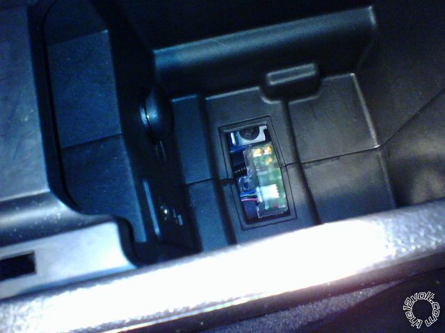
Posted: March 21, 2010 at 9:44 PM / IP Logged  
New problem. I guess it's not really new, just didn't think about it till now.  I have a tilt sensor and a glass breakage sensor. I diode isolated them and tapped into the trunk trigger  (blue H1/7 wire). Problem: the trunk trigger is the same system as the door triggers. Neg. Norm Closed. Trunk trigger worked fine by itself, but alarm won't go off for these two new sensors. the DTIMAZDA fixed my door trigger problem.  I'm thinking if I get another DTIMAZDA module and use two of the four inputs on the trigger side of the module for the sensors and not use the outputs (not needed) on the DTIMAZDA,  that should work. Does this sound correct? Thanks
monty862 
Copper - Posts: 116
Copper spaceThis member has made a donation to the12volt.com. Click here for more info.spacespace
Joined: December 10, 2009
Location: Kentucky, United States
Posted: March 21, 2010 at 9:54 PM / IP Logged  

After I thought about it some more, I think I'll have to use one ot the DTIMAZDA trigger inputs for the trunk trigger. And the corresponding DTIMAZDA output to the SJB. Correct?

Page of 5

  Printable version Printable version Post ReplyPost New Topic
You cannot post new topics in this forum
You cannot reply to topics in this forum
You cannot delete your posts in this forum
You cannot edit your posts in this forum
You cannot create polls in this forum
You cannot vote in polls in this forum

  •  
Search the12volt.com
Follow the12volt.com Follow the12volt.com on Facebook
Wednesday, May 8, 2024 • Copyright © 1999-2024 the12volt.com, All Rights Reserved Privacy Policy & Use of Cookies
Disclaimer: *All information on this site ( the12volt.com ) is provided "as is" without any warranty of any kind, either expressed or implied, including but not limited to fitness for a particular use. Any user assumes the entire risk as to the accuracy and use of this information. Please verify all wire colors and diagrams before applying any information.

Secured by Sectigo
the12volt.com spacer
Support the12volt.com
Top
the12volt.com spacer