the12volt.com spacer
icon

Viper 5901, 95 Pontiac Trans Am


Post ReplyPost New Topic
< Prev Topic Next Topic >
x1le 
Copper - Posts: 171
Copper spacespace
Joined: August 01, 2009
Location: Massachusetts, United States
Posted: February 11, 2010 at 9:31 AM / IP Logged  
The remote starter portion is literally just hooking the h3 harness. If you were able to successfully integrate the alarm portion, remote start is just a few more wires...
ssbowtie1 
Copper - Posts: 74
Copper spacespace
Joined: January 11, 2010
Location: California, United States
Posted: February 11, 2010 at 9:37 AM / IP Logged  
OK fair enough. Let me get the alarm working and I'll probably tackle the remote start with some guidance from you all.
tommy... 
Gold - Posts: 1,901
Gold spacespace
Joined: December 10, 2004
Location: United States
Posted: February 11, 2010 at 5:12 PM / IP Logged  

ssbowtie1 wrote:
Thanks monty the directions were pretty clear regarding cutting the ignition wire and that's what I will do.
Regarding the remote start, it is absolutely a useful feature, especially on this car where the heater takes a long time to warm up and its always a good idea to warm the engine before driving so I usually end up sitting in a cold car waiting for it to warm up.
However, this is my first alarm install and although I haven't started the car yet, I feel confident that i will not have many issues. I would feel much more comfortable, however, having someone around that is more experienced if I am going to install a remote start. I already have the VATS bypassed for other reasons, its a simple resistor that I soldered to the ignition switch.
I may just get quotes on installing the remote switch or maybe after doing some more research I'll feel more comfortable and tackle the remote start at a later time.

First of all...Do NOT cut the Ignition wire...Rather the starter wire...! Also you might have trouble finding a shop to just hook up the remote starter portion as the price will probably be almost the same...And they might be reluctant that you installed part of it ...(honoring a warranty on labor...If something went wrong...Probably go something like"well you installed the alarm portion and thats what caused the issue,so another $150 please")

M.E.C.P & First-Class
Go slow and drink lots of water...Procrastinators' Unite...Tomorrow!
ssbowtie1 
Copper - Posts: 74
Copper spacespace
Joined: January 11, 2010
Location: California, United States
Posted: February 11, 2010 at 9:39 PM / IP Logged  
Yea I meant to say the starter wire :)
Well I'm glad to say I've successfully installed the alarm. The only thing that doesn't seem to be working is the shock sensor. I do have the alarm zip tied to a piece of plastic between the body and the panel though so that might be a problem. I simply can't find an open surface on the body or under the dash to mount the alarm to.
Anyway, I've decided I might want to tackle the remote start, however I still don't know what the flex relay is or if I need it so if someone would be so kind to elaborate on that and if anyone has any advice on wiring a remote start to a manual I'd love to hear it.
x1le 
Copper - Posts: 171
Copper spacespace
Joined: August 01, 2009
Location: Massachusetts, United States
Posted: February 11, 2010 at 9:48 PM / IP Logged  
the flex relay is basically a pre-wired relay inside the brain. If you were to think of it as a regular relay the RED / white is 30 and the pink/white is 87. It can be used to trigger extra starter, ignition, or accessory wires.
It looks like you have a (+)2nd ignition in your vehicle, so you will connect the RED / white to 12v and the pink/white to the 2nd ignition wire.
The rest is pretty straight forward. Red to 12v, pink to ignition, orange to accessory, and you already got the starter hooked up.
As for the remaining connections, you should already have the door triggers hooked for the alarm so the only other connections you should need besides the h3 harness are going to be the NSS wire, brake wire, and tach. You also will need to bypass the clutch during remote start, which you can probably do a search on.
ssbowtie1 
Copper - Posts: 74
Copper spacespace
Joined: January 11, 2010
Location: California, United States
Posted: February 12, 2010 at 9:21 AM / IP Logged  
Thanks x1le so I guess that means I don't need H3/8 (+) FLEX RELAY INPUT 87A key side (if required) of FLEX RELAY.
All the other wires seem straight forward. The only thing is manuals don't have a neutral safety switch? So do I hook this wire up to the ebrake wire as stated?
I'll do a search on bypassing the clutch to learn more.
Thanks everyone I never thought I'd install a remote start but with your help its starting to seem more realistic.
x1le 
Copper - Posts: 171
Copper spacespace
Joined: August 01, 2009
Location: Massachusetts, United States
Posted: February 12, 2010 at 10:06 AM / IP Logged  
No problem man.
yep you don't need the pink/black and yes, you would hook the NSS up to your ebrake.
As far as the clutch, it's been covered a bunch of times on the forum, but basically you should have a wire that go's to ground when the clutch is engaged. You just need to send this wire a negative pulse when remote starting. I would use the (-) starter output from the remotestart.
ssbowtie1 
Copper - Posts: 74
Copper spacespace
Joined: January 11, 2010
Location: California, United States
Posted: February 12, 2010 at 12:36 PM / IP Logged  
Thanks again x1le.
The main problem I'm having now is how to get +12V to the 3 heavy gauge wires. Each of these wires has a 30A fuse so we're talking a total of potentially 90A! Plus there's the main alarm power which is another 15A. I can't imagine its ok to just splice all these wires into the +12 at the ignition harness, so does everyone just run a large gauge wire from the batt or a dist. block to hook these wires up? My battery is in the front pass side, so I would have to run a long wire to get it to the driver's side where all these wire will be.
monty862 
Copper - Posts: 116
Copper spaceThis member has made a donation to the12volt.com. Click here for more info.spacespace
Joined: December 10, 2009
Location: Kentucky, United States
Posted: February 12, 2010 at 7:57 PM / IP Logged  
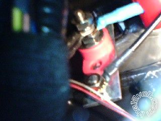
That is what I did. I could have tapped into a large 120 amp feed that goes to my smart junction box. However, I have a new car and I still cringe whenever I have to splice a wire. I bought a 3/8" terminal post and attached it to a 1.25" inch wide steel strip. I had a unused stud that protruded from the firewall and attached the strip to that. I ran a 8 gauge wire from the battery to the post. It has an inline fuse near the battery. I ran all my 12 volt wires to the terminal post. I also drilled a 1/4" hole in the steel strap and put a bolt in there to use for my ground wires. Ran a ground wire from the neg battery cable pigtail to that bolt. I have a rubber cap that covers the terminal. A lot of time involved, but I'm happy with the result.
Viper 5901, 95 Pontiac Trans Am - Page 2 -- posted image.
tommy... 
Gold - Posts: 1,901
Gold spacespace
Joined: December 10, 2004
Location: United States
Posted: February 12, 2010 at 8:15 PM / IP Logged  

Did you mount the shock sensor...I usually find a big harness and zip-tie it to the big wire loom...Ive noticed it being not sensitive and waaayyy to sensitive mounting directly to the metal...Other times it has worked fine...But usually right to a big fat loom of wires...!

M.E.C.P & First-Class
Go slow and drink lots of water...Procrastinators' Unite...Tomorrow!
Page of 11

  Printable version Printable version Post ReplyPost New Topic
You cannot post new topics in this forum
You cannot reply to topics in this forum
You cannot delete your posts in this forum
You cannot edit your posts in this forum
You cannot create polls in this forum
You cannot vote in polls in this forum

  •  
Search the12volt.com
Follow the12volt.com Follow the12volt.com on Facebook
Monday, April 29, 2024 • Copyright © 1999-2024 the12volt.com, All Rights Reserved Privacy Policy & Use of Cookies
Disclaimer: *All information on this site ( the12volt.com ) is provided "as is" without any warranty of any kind, either expressed or implied, including but not limited to fitness for a particular use. Any user assumes the entire risk as to the accuracy and use of this information. Please verify all wire colors and diagrams before applying any information.

Secured by Sectigo
the12volt.com spacer
Support the12volt.com
Top
the12volt.com spacer