the12volt.com spacer
icon

2003 chevy silverado viper 5301 wiring


Post ReplyPost New Topic
< Prev Topic Next Topic >
ericsigman 
Member - Posts: 13
Member spacespace
Joined: December 12, 2010
Posted: December 13, 2010 at 7:24 AM / IP Logged  

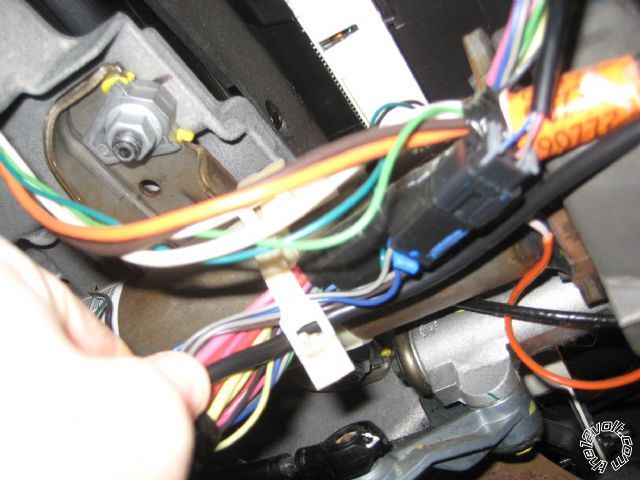
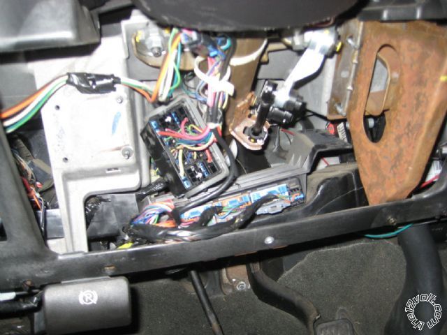
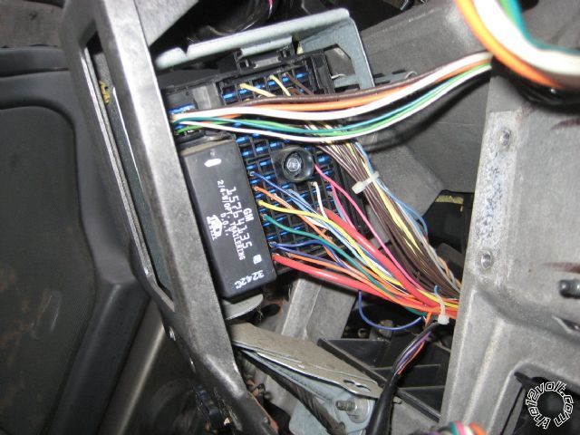
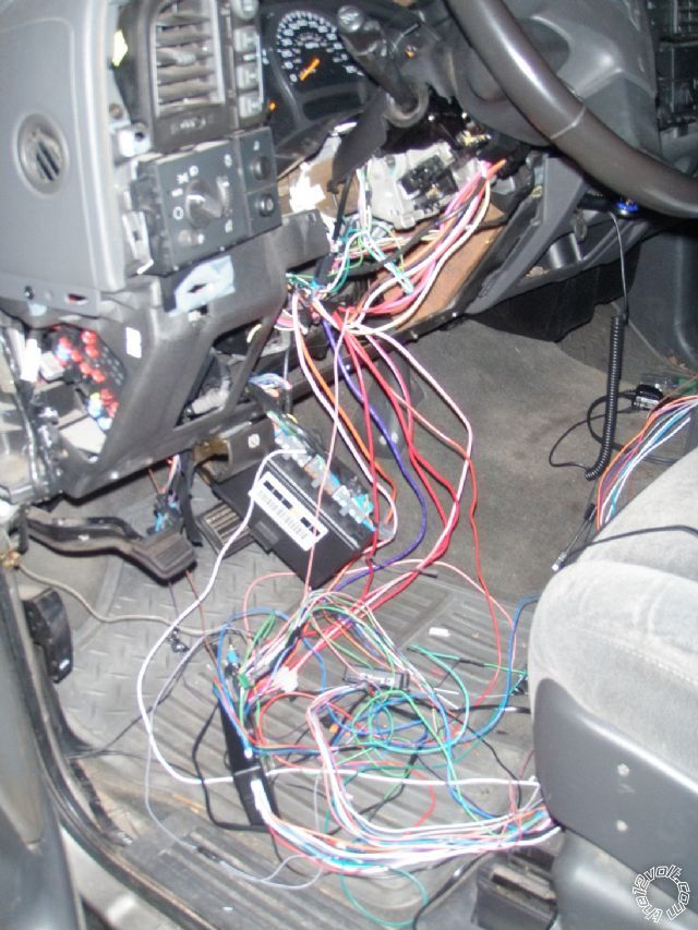
I am about to start cutting wires and soldering on my 2003 Silverado to install the Viper 5301 remote start. Below are a few pictures of the dash taken apart. I was wondering if anyone had a picture of thoie viper remote start installed so i could see where ther ran the wires. This is my first remote start but from the pictures, is it the large guage wires (red, yellow, white, pink, orange, and brown) i will be conecting to? Also can i tap in right there or does it have to be behind/ on the back side of the harness? Thanks for the help

2003 chevy silverado viper 5301 wiring -- posted image.

2003 chevy silverado viper 5301 wiring -- posted image.

2003 chevy silverado viper 5301 wiring -- posted image.

chriswallace187 
Gold - Posts: 1,661
Gold spacespace
Joined: March 11, 2002
Location: Pennsylvania, United States
Posted: December 13, 2010 at 10:06 AM / IP Logged  
You're on the right track. I'll comment more later when I can mark your photos - what part are you using for the door lock interface and/or Passlock bypass?
C Renner's Auto Electronix
My service is cheap, quick, and good - pick any two
ericsigman 
Member - Posts: 13
Member spacespace
Joined: December 12, 2010
Posted: December 13, 2010 at 10:38 AM / IP Logged  
Thanks for the reply...i am a total newbie when it comes to electronics. I have the DLPKGM moduale that i was going to do D2D but after reading these posts, i think im gonna do W2W. Any help is apreciated and i can take more pics if that will help.
ericsigman 
Member - Posts: 13
Member spacespace
Joined: December 12, 2010
Posted: December 14, 2010 at 9:11 AM / IP Logged  

Also, I have a peripheral PGMDLBP bypass. I bought this one first but decided to go with the xpresskit because it was made by DEI like the Viper. Any input on the Peripheral?

chriswallace187 
Gold - Posts: 1,661
Gold spacespace
Joined: March 11, 2002
Location: Pennsylvania, United States
Posted: December 14, 2010 at 12:08 PM / IP Logged  
That Peripheral piece is a rebadged Bypasskit part, possibly designed by one of the same engineers who did the DLPKGM. It should work just fine.
I'd use whatever bypass that would be harder to return/less expensive.
Either one of those bypasses connect at the OBDII plug, so you don't need to worry about finding the Passlock wires.
Also, the BCM will slide out towards the driver's seat, and you can maneuver it down towards the brake pedal. IMHO that makes it easier to connect wires there.
C Renner's Auto Electronix
My service is cheap, quick, and good - pick any two
ericsigman 
Member - Posts: 13
Member spacespace
Joined: December 12, 2010
Posted: December 14, 2010 at 1:20 PM / IP Logged  

Sorry for "stupid" questions but is the BCM the black box in the middle of the 2nd picture? Does it disconnect? I think i have seen this in another install picture but it looked like it was the back side of the box, not the side i can see in the picture? This should be where i connect the H3 harness wire, right.

The DLPKGM wires seem straight forward to the truck, i just need the black ground to kick panel and the Purple to the purple wire on the 2 pin OBD II correct?

Also, i have read that i should disconnect the battery AND that i shouldnt disconnect? I always thought it was safer to disconnect?

Thanks for the help guys...I'm gonna start the install tonught after work.

ericsigman 
Member - Posts: 13
Member spacespace
Joined: December 12, 2010
Posted: December 14, 2010 at 10:02 PM / IP Logged  

OK guys. I got everything hooked up tonight. Right now it is just put in place and wrapped with elec tape. I plan on soldering everything once i figure out whats going on. I hooked the battery up but i'm not sure how to go about programing it. I'm in VA and its 16 deg outside (they say 2 deg with wind chill) so i called it a night. When i tried to lock and unlock the lights blinked indie and headlight but it wouldnt lock or unlock. Also, the remote start gave me the error beep and then had 7 flashes? I will have all night tomorrow to work on it if you can point me in the right direction.

Thanks for the input.

ericsigman 
Member - Posts: 13
Member spacespace
Joined: December 12, 2010
Posted: December 15, 2010 at 8:55 PM / IP Logged  

Well i tried to get things programed today but no luck. I'm lost... I have all the wires hooked up. I'm not sure where to start. The lock and unlock isnt working and the remote start just gives me the 7 flashes error. I giess i'll start with the wires i have connected:

H/3

1 Pink to Pinka @ IGN

2 RED / White to Red @ IGN ( This Red is between the Pink & Bron at IGN)
3 Orange to Orange @ IGN
4 Violet to Yellow @ IGN
5 Red to Red @ IGN ( This Red is between Orange & White at IGN)
6 Pink/White to White @ IGN
7 Pink/Black N/A
8 RED / Black to Red (Same Red as #5 above - Red between Orange & White at IGN)

H/1

1 RED / white

2 Red to Red @ IGN (Same Red as #5 & #8 above - Red between Orange & White at IGN)
3 Brown n/a
4 WHITE/ brown - n/a
5 Black to Ground i made at Kick panel
6 violet - n/A
7 blue - n/A
8 Green to Green at DLPKGM
9 BLACK/ white - n/a
10 WHITE/ blue - n/a
11 White to Grey/Black at BCM(in brown plug)
12 orange -n/a

H/2

1 light/green -

2 ORANGE / black -
3 GREEN / WHITE -
4 violet/black -
5 WHITE/ black -
6 WHITE/ violet -
7 grey/black -
8  empty
9 Violet/White to Violet/White at DLPKGM BUT this isn't hooked up to anything right now
10 dark blue -
11 pink/white -
12 orange -
13 purple -
14 pink -
15 Grey to Hood Pin
16 blue/white -
17 Brown to White at Break Pedal
18 BLACK/ White to ground @ Kick Panel (same ground as H/1 5 above)

DLPKGM

Pink to Pink @ IGN

Purple to Purple @ OBD II
Blue to Unlock at Viper
Light Green to Lock at Viper

Violet/White - This is NOT hooked up? I dont know if i need this/ not sure what tach i am running.

Any help would be appreciated.

smokeman1 
Platinum - Posts: 1,588
Platinum spaceThis member has made a donation to the12volt.com. Click here for more info.spaceThis member has been recognized as an authority in Mobile Security and Convenience. Click here for more info.spacespace
Joined: September 14, 2009
Location: Wisconsin, United States
Posted: December 15, 2010 at 9:40 PM / IP Logged  
Are you saying that you have two RED Constant 12volts at the ignition?  Bulldog lists only one.  7 flashes means the unit is in the Manual Mode. Needs to be changed to AUTOMATIC if your truck is an auto.  Menu 3, Item 1, Option 2.
When all else fails, Read the Instructions
Support the12volt.com Make a Donation
ericsigman 
Member - Posts: 13
Member spacespace
Joined: December 12, 2010
Posted: December 15, 2010 at 10:50 PM / IP Logged  

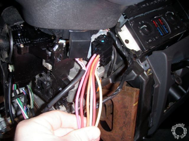
Below is a picture of my IGN harness and the wiress i am slicing into. There is also a Brown in the IGN that is hidden but it has nothing going to it. The  H/3 2 RED / White is connected @ Red IGN ( the IGN switch has 7 wires: 3 on the top Pink - Red - Brown and 4 on the bottom White - Yellow - Red - Orange) This H/3 2 RED / white is connected to the red on the top row. The H/3 5 Red & 8 RED / Black are connected to the Red IGN on the bottom row.

2003 chevy silverado viper 5301 wiring -- posted image.

Here is a picture of how the truck looks tonight:

2003 chevy silverado viper 5301 wiring -- posted image.

Also, i'm still confused on how to change it from Manual to Auto. Do i need to have the DLPKGM hooked up for this and should i have to program the remote? Right noe when i have the control plug hooked up, it constantly blinks blue. I also have the jumpers on the Viper vertical. Is this correct?

And, do i need the  Violet/whiteTach wire hooked up coming from the DLPKGM(its not right now)? I have the door lock and unlock hooked upfrom the DLPKGM to the viper 3 PIN. I'm using the D2D now, should i go W2W?

Thanks for the help!

Thanks

Page of 2

  Printable version Printable version Post ReplyPost New Topic
You cannot post new topics in this forum
You cannot reply to topics in this forum
You cannot delete your posts in this forum
You cannot edit your posts in this forum
You cannot create polls in this forum
You cannot vote in polls in this forum

  •  
Search the12volt.com
Follow the12volt.com Follow the12volt.com on Facebook
Friday, April 19, 2024 • Copyright © 1999-2024 the12volt.com, All Rights Reserved Privacy Policy & Use of Cookies
Disclaimer: *All information on this site ( the12volt.com ) is provided "as is" without any warranty of any kind, either expressed or implied, including but not limited to fitness for a particular use. Any user assumes the entire risk as to the accuracy and use of this information. Please verify all wire colors and diagrams before applying any information.

Secured by Sectigo
the12volt.com spacer
Support the12volt.com
Top
the12volt.com spacer