the12volt.com spacer
icon

First Alarm, 97 Honda Civic


Post ReplyPost New Topic
< Prev Topic Next Topic >
howie ll 
Pot Metal - Posts: 16,466
Pot Metal spacespace
Joined: January 09, 2007
Location: United Kingdom
Posted: May 27, 2011 at 11:41 AM / IP Logged  
You should pick up the starter AFTER the clutch switch, but that's an assumption on my part because apart from some Toyotas we don't have them in Europe* maybe Kreg or KP can help here.
*That's the US version of our 'Elf and Safety jobsworthies.
zerovandez 
Copper - Posts: 115
Copper spacespace
Joined: March 22, 2008
Location: California, United States
Posted: May 27, 2011 at 12:00 PM / IP Logged  

There's an MTS (manual transmission mode) that these units must learn before using on a MT car. The remote start won't work unless I complete this processes. Hopefully, this process will bypass the clutch switch internally some how or maybe another user can chime in.

howie ll 
Pot Metal - Posts: 16,466
Pot Metal spacespace
Joined: January 09, 2007
Location: United Kingdom
Posted: May 27, 2011 at 12:18 PM / IP Logged  
No it won't. The switch has to "see" the clutch depressed.
Is there a BLACK/ white lead as one of the 2 coming out of that switch? If so cut it and wire you green starter input to the clutch switch side and your violet starter output to the other side.
zerovandez 
Copper - Posts: 115
Copper spacespace
Joined: March 22, 2008
Location: California, United States
Posted: May 27, 2011 at 12:35 PM / IP Logged  
I guess there's a BLUE and BLACK wire to the clutch switch which activates the ignition. When the clutch pedal is pressed, this switch completes a ground circuit. I suppose I can just join the 2 wires together and bypass the switch completely but I think that's pretty dangerous. Somehow I think a relay is needed here but I have not a clue how they work or if it's possible for this application lol.
howie ll 
Pot Metal - Posts: 16,466
Pot Metal spacespace
Joined: January 09, 2007
Location: United Kingdom
Posted: May 27, 2011 at 12:43 PM / IP Logged  
OK, disconnect the leads and see if the car still starts when you press in the clutch. If it doesn't you have the right wires.
Now check those wires with your DMM, one should be at ground the other go to ground when the clutch is depressed.
The one that goes to ground when the clutch is depressed, connect to your status output wire, A.K.A. Ground When Running or GWR wire. Job done.
If one measures 12V+ and the other goes top 12V+ when the switch is depressed, let me know.
zerovandez 
Copper - Posts: 115
Copper spacespace
Joined: March 22, 2008
Location: California, United States
Posted: May 27, 2011 at 2:42 PM / IP Logged  

Fact of the matter is that I'm not doing the install at the moment although I do have the car completely gutted. I'm gathering as much info as I can to prepare myself. So with everyones input, i'm able to make a better diagram as to where and how I should route things. I'm really "in-tune" with my car and can confirm that the clutch pedal wires are in fact grounding and true to color as I stated but I'll check later tonight when I'm home.

So on the REMOTE START AUX OUTPUT 5 PIN CONNECTOR, there is a blue wire labeled (-)200mA STATUS OUTPUT. I assume this is the lead that you're referring to. Does this need to splice into the "ground when depressed" wire? Or cut and rerouted?

Thanks for your patience and all of your help!

howie ll 
Pot Metal - Posts: 16,466
Pot Metal spacespace
Joined: January 09, 2007
Location: United Kingdom
Posted: May 27, 2011 at 4:46 PM / IP Logged  
Yes That blue "status output" wire goes to the wire that goes to ground when the clutch pedal is depressed. You can try to test this by grounding that wire, then see if you can start the car without depressing the clutch pedal having made sure you're in neutral first.
zerovandez 
Copper - Posts: 115
Copper spacespace
Joined: March 22, 2008
Location: California, United States
Posted: May 31, 2011 at 1:00 PM / IP Logged  

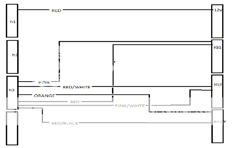
So this is what I have so far. Keep in mind these are just power wires according to what I'm reading from the install manual. Yes, I will add fuses. What do you all think?

First Alarm, 97 Honda Civic - Page 3 -- posted image.

zerovandez 
Copper - Posts: 115
Copper spacespace
Joined: March 22, 2008
Location: California, United States
Posted: May 31, 2011 at 1:04 PM / IP Logged  

Sorry, here's a bigger picture

First Alarm, 97 Honda Civic - Page 3 -- posted image.

kreg357 
Platinum - Posts: 7,783
Platinum spaceThis member has made a donation to the12volt.com. Click here for more info.spaceThis member has been recognized as an authority in Electrical Theory. Click here for more info.spaceThis member has been recognized as an authority in Mobile Security and Convenience. Click here for more info.spacespace
Joined: January 30, 2009
Location: Pennsylvania, United States
Posted: May 31, 2011 at 1:18 PM / IP Logged  
No. The H3 wires, Red, RED / White and RED / Black all go to +12 constant just like the H1/2 Red wire.
Soldering is fun!
Page of 17

  Printable version Printable version Post ReplyPost New Topic
You cannot post new topics in this forum
You cannot reply to topics in this forum
You cannot delete your posts in this forum
You cannot edit your posts in this forum
You cannot create polls in this forum
You cannot vote in polls in this forum

  •  
Search the12volt.com
Follow the12volt.com Follow the12volt.com on Facebook
Thursday, April 25, 2024 • Copyright © 1999-2024 the12volt.com, All Rights Reserved Privacy Policy & Use of Cookies
Disclaimer: *All information on this site ( the12volt.com ) is provided "as is" without any warranty of any kind, either expressed or implied, including but not limited to fitness for a particular use. Any user assumes the entire risk as to the accuracy and use of this information. Please verify all wire colors and diagrams before applying any information.

Secured by Sectigo
the12volt.com spacer
Support the12volt.com
Top
the12volt.com spacer