the12volt.com spacer
icon

First Alarm, 97 Honda Civic


Post ReplyPost New Topic
< Prev Topic Next Topic >
zerovandez 
Copper - Posts: 115
Copper spacespace
Joined: March 22, 2008
Location: California, United States
Posted: August 17, 2011 at 9:00 AM / IP Logged  
Thanks. The battery is dead again and I will def test once it's charged. And while I'm finishing things up and the car still apart. Do you know of a relay diagram that would allow me to setup "priority unlock" where the driver side unlocks first? I couldn't find any with my searches.
howie ll 
Pot Metal - Posts: 16,466
Pot Metal spacespace
Joined: January 09, 2007
Location: United Kingdom
Posted: August 17, 2011 at 10:44 AM / IP Logged  
Try this, notice I'm using the motor wires in each case.
Z53_priority_unlock.bmp
zerovandez 
Copper - Posts: 115
Copper spacespace
Joined: March 22, 2008
Location: California, United States
Posted: August 18, 2011 at 8:19 AM / IP Logged  

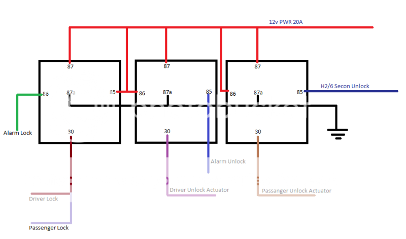
Thanks. So after looking at the relay diagram here, and another relay diagram for the 2nd unlock else where, I came up with this;

First Alarm, 97 Honda Civic - Page 8 -- posted image.

howie ll 
Pot Metal - Posts: 16,466
Pot Metal spacespace
Joined: January 09, 2007
Location: United Kingdom
Posted: August 18, 2011 at 9:08 AM / IP Logged  
Which will blow all your fuses!
In my CORRECT diagram, 87a is the control side and 30 is the door side, you cut those motor wires and join to 87a and 30. UNLESS... you are going to completely control it from the alarm, and disregard the factory control unit then you're correct.
zerovandez 
Copper - Posts: 115
Copper spacespace
Joined: March 22, 2008
Location: California, United States
Posted: August 18, 2011 at 9:31 AM / IP Logged  

LOL! My car doesn't have factory alarm and/or keyless entry. I'm using aftermarket 2 wire actuators.

howie ll 
Pot Metal - Posts: 16,466
Pot Metal spacespace
Joined: January 09, 2007
Location: United Kingdom
Posted: August 18, 2011 at 9:40 AM / IP Logged  
Then use YOUR diagram, it's fine.
zerovandez 
Copper - Posts: 115
Copper spacespace
Joined: March 22, 2008
Location: California, United States
Posted: August 19, 2011 at 10:56 AM / IP Logged  
Finally, I feel that I've got something right haha! So after reading a few others installation posts about this kind of alarm, I've come to find I'm learning about H3/3 Accessory Output (+). I was originally thinking this wire is supposed to be connected to the Accy wire on the Ignition switch but after some reading and common sense, I'm finding out that this is probably incorrect. The install guide says to connect it to the Accy wire that powers the climate control unit but the alarm, in my case, will not have anything to do with the climate control other than the defrost output. So should I even connet this to anything? I really don't see a need for it.
howie ll 
Pot Metal - Posts: 16,466
Pot Metal spacespace
Joined: January 09, 2007
Location: United Kingdom
Posted: August 19, 2011 at 10:58 AM / IP Logged  
It's optional.
zerovandez 
Copper - Posts: 115
Copper spacespace
Joined: March 22, 2008
Location: California, United States
Posted: August 23, 2011 at 9:12 PM / IP Logged  
So after careful observation and research, I find that my Python 991 is a newer version with a 16 pin harness as opposed to what was offered prior, which had a few AUX harnesses. My main concern is that my "newer" model does NOT have a 2nd unlock output! Ive been following the manual online but didn't notice that until I went to connect everything up. Is there anything I can do which would allow for a 2nd unlock output on my newer python 991? And no, I wouldn't want to use any AUX commands for a 2nd unlock.
zerovandez 
Copper - Posts: 115
Copper spacespace
Joined: March 22, 2008
Location: California, United States
Posted: August 23, 2011 at 10:25 PM / IP Logged  
So I think I found my answer after more reading. I downloaded the manual for the Viper 5701 w/new H2 connector and it's just like my new version python 991. The features menu lists any AUX output can be programed as 2nd unlock. Here is the description:
2nd unlock: the wire will operate as 2nd unlock and will not activate for remote control commands.
I'm not understanding what "will not activate for remote control commands" mean. Can anyone verify that I'm on the right path? Thanks!
Page of 17

  Printable version Printable version Post ReplyPost New Topic
You cannot post new topics in this forum
You cannot reply to topics in this forum
You cannot delete your posts in this forum
You cannot edit your posts in this forum
You cannot create polls in this forum
You cannot vote in polls in this forum

  •  
Search the12volt.com
Follow the12volt.com Follow the12volt.com on Facebook
Saturday, April 20, 2024 • Copyright © 1999-2024 the12volt.com, All Rights Reserved Privacy Policy & Use of Cookies
Disclaimer: *All information on this site ( the12volt.com ) is provided "as is" without any warranty of any kind, either expressed or implied, including but not limited to fitness for a particular use. Any user assumes the entire risk as to the accuracy and use of this information. Please verify all wire colors and diagrams before applying any information.

Secured by Sectigo
the12volt.com spacer
Support the12volt.com
Top
the12volt.com spacer