


2007 toyota highlander, remote start
Home /
the12volt's Install Bay /
Car Security and Convenience / 2007 toyota highlander, remote start ( Topic Closed)


Posted: January 13, 2012 at 10:41 AM / IP Logged


Posted: January 13, 2012 at 1:15 PM / IP Logged
Posted: January 13, 2012 at 1:40 PM / IP Logged
Posted: January 13, 2012 at 6:01 PM / IP Logged
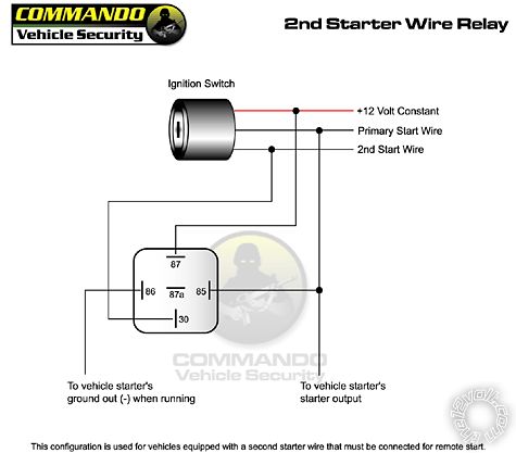 The only thing I would change is connecting Pin 86 directly to ground instead of using the "ground out when running" wire as that one might be used for the immobilizer bypass.
Posted: January 13, 2012 at 7:44 PM / IP Logged
Posted: January 13, 2012 at 7:48 PM / IP Logged
Posted: January 13, 2012 at 7:52 PM / IP Logged
Posted: January 13, 2012 at 7:57 PM / IP Logged
Posted: January 13, 2012 at 8:10 PM / IP Logged
Posted: January 13, 2012 at 9:32 PM / IP Logged
 Printable version
| You cannot post new topics in this forum You cannot reply to topics in this forum You cannot delete your posts in this forum You cannot edit your posts in this forum You cannot create polls in this forum You cannot vote in polls in this forum |

| Search the12volt.com |
Follow the12volt.com 
Saturday, April 25, 2026 • Copyright © 1999-2026 the12volt.com, All Rights Reserved • Privacy Policy & Use of Cookies

Saturday, April 25, 2026 • Copyright © 1999-2026 the12volt.com, All Rights Reserved • Privacy Policy & Use of Cookies
Disclaimer:
*All information on this site ( the12volt.com ) is provided "as is" without any warranty of any kind, either expressed or implied, including but not limited to fitness for a particular use. Any user assumes the entire risk as to the accuracy and use of this information. Please
verify all wire colors and diagrams before applying any information.
