the12volt.com spacer
icon

omega au 93 4 window rollup .


Post ReplyPost New Topic
< Prev Topic Next Topic >
1prix 
Member - Posts: 24
Member spacespace
Joined: October 07, 2012
Location: Pennsylvania, United States
Posted: October 13, 2012 at 2:37 PM / IP Logged  
Question-i hooked up the window module to 1 window just to test its operation.
I connected it to the orange starter output wire that should be ground when armed.But when i hit arm it does nothing, lol but when i remote start the car or start the car with the key the window rolls up by itself.
What am i doing wrong
Now when i take the rely out of the relay holder it works like it should.
i am 99.99% sure i have the starter interrupter connected properly because it works like it should.(it does not allow me to start the car when armed or when the alarm is going off)
howie ll 
Pot Metal - Posts: 16,466
Pot Metal spacespace
Joined: January 09, 2007
Location: United Kingdom
Posted: October 13, 2012 at 7:09 PM / IP Logged  
Orange wire, diode thus using 2 x 1N4004:- 887_starter_cut.bmp
offroadzj 
Gold - Posts: 2,043
Gold spaceThis member has made a donation to the12volt.com. Click here for more info.spaceThis member has been recognized as an authority in Mobile Security and Convenience. Click here for more info.spacespace
Joined: June 03, 2005
Location: New York, United States
Posted: October 13, 2012 at 7:27 PM / IP Logged  
A little off topic (but still related). On my python 990 I have the same issue with the windows rolling up on remote start. On this unit though the starter kill relay is internal. Is the GWA wire internally connected without diodes to that starter kill? Will putting a diode on the orange wire heading to the 530t prevent the window roll-up?
Kenny
Owner / Technician
KKD Garage LLC
Albany, NY 12205
1prix 
Member - Posts: 24
Member spacespace
Joined: October 07, 2012
Location: Pennsylvania, United States
Posted: October 13, 2012 at 9:17 PM / IP Logged  
howie ll wrote:
Orange wire, diode thus using 2 x 1N4004:- 887_starter_cut.bmp
i am really not understanding what you are talking about.this was my first alarm install.I have some 1N4005 diodes and why two.My starter kill came with a built in diode. I really don't want to ditch the starter kill.
1prix 
Member - Posts: 24
Member spacespace
Joined: October 07, 2012
Location: Pennsylvania, United States
Posted: October 13, 2012 at 11:50 PM / IP Logged  
omega au 93 4 window rollup . -- posted image.
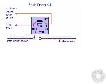
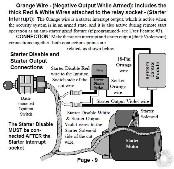
This is how my starter interrupter is wired.
What would i need to do.
1prix 
Member - Posts: 24
Member spacespace
Joined: October 07, 2012
Location: Pennsylvania, United States
Posted: October 14, 2012 at 12:01 AM / IP Logged  
what's your email i want to send you a picture of how my starter interrupter is wired.
Then maybe you can add or change what needs to be done.
would the IN4005 diodes work?
i would like to get this done by monday.
Thank you very much
I tried to send you a private pm offroadzj i think your box is full.
howie ll 
Pot Metal - Posts: 16,466
Pot Metal spacespace
Joined: January 09, 2007
Location: United Kingdom
Posted: October 14, 2012 at 3:41 AM / IP Logged  
Right hand side of the drawing, ORANGE wire from "system control module" branch out from it using your available diode.
A 1N4005 is fine but what worries me is that diagram already shows a diode.
Ha, I've just realised, that that diagram is wrong and the one I showed you is right! That's why you're getting problems!
In the diagram do you see an ignition wire going to that relay????
Correct wiring:-
Orange GWA to 85 via diode (as shown, if not 1N4005 is fine, band towards control module.
Cut vehicle starter wire.
Key side to 87a.
Motor side + violet from control module to 30
IGNITION 1 to 86.
Kenny, it should be internally dioded but it does come from "let's make it cheaper" DEI.
howie ll 
Pot Metal - Posts: 16,466
Pot Metal spacespace
Joined: January 09, 2007
Location: United Kingdom
Posted: October 14, 2012 at 3:47 AM / IP Logged  
If none of the above works check your wiring and especially check the voltage across the power inputs and ground.
What worries me is "I'm not really understanding what you're talking about, this was my first alarm".
Apart from correcting your English what you said is sending shivers of trepidation down my spine. Will I hear the bang from 3000+ miles away?
1prix 
Member - Posts: 24
Member spacespace
Joined: October 07, 2012
Location: Pennsylvania, United States
Posted: October 14, 2012 at 4:52 AM / IP Logged  
Everybody has their first time doing anything. I have read a read a hooded up the alarm per the installation manual,so if the starter interrupter is wrong that is how the manual says to do it.
And what i meant was that i can't understand your diagram it looks confusing but i understand the basic startkill diagram in the relay section of this forum.
I haven't taken classes for installing alarms/remote starters but a can read and follow directions if explained clearly.
so i guess i will use this
omega au 93 4 window rollup . -- posted image.
howie ll 
Pot Metal - Posts: 16,466
Pot Metal spacespace
Joined: January 09, 2007
Location: United Kingdom
Posted: October 14, 2012 at 5:10 AM / IP Logged  
Which is exactly what I just told you to do except per international convention (ISO) 85 and 86 are the other way round, in practise it doesn't matter but that's how the motor manufacturers do it.
As an alternative the diode across the middle can also be run inline on the orange wire.
Just check to see if your R/S manufacturer has wired it the same way.
The point I was making is that the original diagram you very nicely printed makes no mention of ignition feed to 86 (or in this case 85).
Classes are a load of rubbish, it's the "hands-on" experience you're getting now that counts.
Just a couple of points to remember though I must admit you seem to be doing them, test and verify and don't box up until done and dusted.
Can I assume you're soldering all your joints after testing?
Page of 2

  Printable version Printable version Post ReplyPost New Topic
You cannot post new topics in this forum
You cannot reply to topics in this forum
You cannot delete your posts in this forum
You cannot edit your posts in this forum
You cannot create polls in this forum
You cannot vote in polls in this forum

  •  
Search the12volt.com
Follow the12volt.com Follow the12volt.com on Facebook
Saturday, April 27, 2024 • Copyright © 1999-2024 the12volt.com, All Rights Reserved Privacy Policy & Use of Cookies
Disclaimer: *All information on this site ( the12volt.com ) is provided "as is" without any warranty of any kind, either expressed or implied, including but not limited to fitness for a particular use. Any user assumes the entire risk as to the accuracy and use of this information. Please verify all wire colors and diagrams before applying any information.

Secured by Sectigo
the12volt.com spacer
Support the12volt.com
Top
the12volt.com spacer