the12volt.com spacer
icon

viper 5704 / 2004 mountaineer


Post ReplyPost New Topic
< Prev Topic Next Topic >
flobee4 
Silver - Posts: 585
Silver spacespace
Joined: January 02, 2004
Location: United States
Posted: October 18, 2012 at 6:25 PM / IP Logged  
Ya, even though the 02 and 04 look exactly the same, they are indeed different. All those lights listed in the diagram you uploaded are turned on by computer signals. Can't tap into them like an 02. Sorry to mislead you there. Also that module behind the panel where you posted the picture, on an 02 all the plugs are facing the floor instead of the side. Your year looks alot easier to get to the wires there. As for the hatch release, some diagrams do say that the wire may be purple / YELLOW. SO as long as it tested when the trunk release button on the remote or button in the back hatch was hit, you will be good to go.
vinchinzo 
Copper - Posts: 66
Copper spacespace
Joined: October 11, 2012
Location: Kentucky, United States
Posted: October 18, 2012 at 7:38 PM / IP Logged  
Thanks alot brother you been of great help! I have prepped as much as possible now ima go for it lol I've never installed an alarm before so I been real weary. I'm gonna make a pictorial for others aslong as I'm successful. My only real worry now is programming everything but I think I can do it :)
When in doubt....kick it!
vinchinzo 
Copper - Posts: 66
Copper spacespace
Joined: October 11, 2012
Location: Kentucky, United States
Posted: October 19, 2012 at 10:54 AM / IP Logged  
I have a huge question?? I was out there testing my door triggers so let me make sure I got this right. I set my MM to DC hooked the black to ground then the red to the door trigger opened the door and it shows 12v shut the door and it goes back to 0??? All them door triggers are positive triggers right? My only guess is if I hook them to the H2/6 GREEN (-) DOOR TRIGGER INPUT (N/C* OR N/O) and set it to NC the NC compensates for this? Or am I suppose to run these to H2/12 VIOLET (+) DOOR TRIGGER INPUT??
When in doubt....kick it!
flobee4 
Silver - Posts: 585
Silver spacespace
Joined: January 02, 2004
Location: United States
Posted: October 19, 2012 at 5:10 PM / IP Logged  
Those triggers are ground when closed and open when when the doors are opened. The way I would check that is to put the red probe on a known 12volt source and probe your door triggers with the black.
Still supposed to use green (-) door trigger and change it from default value.
vinchinzo 
Copper - Posts: 66
Copper spacespace
Joined: October 11, 2012
Location: Kentucky, United States
Posted: October 19, 2012 at 9:43 PM / IP Logged  
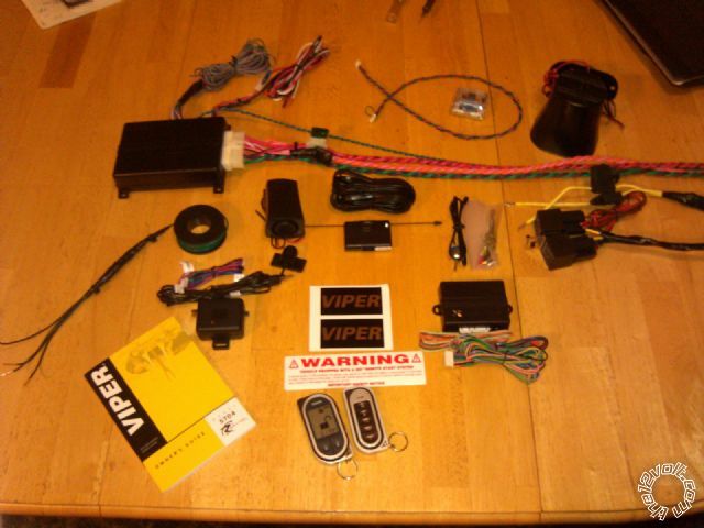
They are indeed negative Kregg helped me out earlier =) Tomorrows the big day lol I hope it goes good here's a pic of my setup I'm all ready. The only wire I haven't found yet is the hatch release and that defrost wire I may just leave the defrost out but it would be nice to walk out to a warm defrosted ride in the winter =)
viper 5704 / 2004 mountaineer - Page 4 -- posted image.
When in doubt....kick it!
kreg357 
Platinum - Posts: 7,783
Platinum spaceThis member has made a donation to the12volt.com. Click here for more info.spaceThis member has been recognized as an authority in Electrical Theory. Click here for more info.spaceThis member has been recognized as an authority in Mobile Security and Convenience. Click here for more info.spacespace
Joined: January 30, 2009
Location: Pennsylvania, United States
Posted: October 20, 2012 at 6:29 AM / IP Logged  

2004 Mountaineer info from Audiovox.  This info conflicts with others, as it lists the signals at (+), while most

list the triggers as N.C. (-), but it does give wire colors & pin locations.  The DMM is your only friend. 

 LF Latch            YELLOW/BLACK (+)         AT CSM MODULE Pin 1

 RF Latch           GRAY/RED (+)   AT CSM MODULE Pin 2  
 LR Latch           LIGHT GREEN/ YELLOW (+)    AT CSM MODULE Pin 9
 RR Latch          PINK/LIGHT BLUE (+)      AT CSM MODULE Pin 7
 Trunk Trigger   WHITE/ VIOLET (+)         AT CSM MODULE Pin 12
 Hood Trigger   TAN/LIGHT GREEN (+)             AT CSM MODULE Pin 11

2004 Mountaineer info from Omega

 Rear Defrost      BROWN / LT.BLUE (+)       AT REAR DEFROST SWITCH

No additional info on this wire.  You will need to locate the wire and test it with the DMM to see if it is a "latched"
output or a single pulse output. Either way you will need a relay to convert the Vipers (-) output to the (+) output
this wire requires.  Also depending on the wires thickness ( current draw ) you might need to use a 30/40 amp rated
relay and fuse accordingly.

 Trunk Release  VIOLET / YELLOW (-)    AT TRUNK RELEASE SWITCH

More conflicting info.  As alway test & verify with a DMM.  On a 2003 Explorer, I found that the rear hatch was
unlocked with the same unlock wire used for the doors.  The Violet / YELLOW wire you located at the CSM, and took a photo
of, seemed to be correct.

Soldering is fun!
vinchinzo 
Copper - Posts: 66
Copper spacespace
Joined: October 11, 2012
Location: Kentucky, United States
Posted: October 20, 2012 at 7:43 AM / IP Logged  
Oh boy lol Im bout to get started I got to run and get a few little things first. About them door triggers I tested them yesterday with the dmm like you guys was saying I set to 20dcv red probe on 12v and the black probe on the door trigger/ With the door shut it read 12v with it open it went down. This would mean it is a negative correct? or is their anyway that could be wrong? im uploading the defogger schematic take a look at it if ya want Im thinking about using the try/lt blu that is before the relay and setting to pulsed or the org / YELLOW? the only brn/lt blue I see is the actual wire going to the defrost grid on the window. I could just leave the defrost out but I really need to figure out the door trigger thing lol
When in doubt....kick it!
vinchinzo 
Copper - Posts: 66
Copper spacespace
Joined: October 11, 2012
Location: Kentucky, United States
Posted: October 20, 2012 at 7:49 AM / IP Logged  
04 Defrost Schematic Heres the schematic im a little good at these things but you may be alot better lol. My plan is to either use the gry/lt blu or the org/yel coming from the Temperature control module. The gry blue leads to a microproccessor of some sort and org/yell comes from that on to the defrost relay...I would think one of them would have to be a pulsed signal. How would I check?
When in doubt....kick it!
flobee4 
Silver - Posts: 585
Silver spacespace
Joined: January 02, 2004
Location: United States
Posted: October 20, 2012 at 8:19 AM / IP Logged  
I didn't look at the schematic, but to test you would but your probe on the suspected wire and hit the button. You will get a reading. Now, did the reading go away when you released the defrost button?(momentary) Or, after you released the button, did you continue to get a reading?(latched). Thats how you test to see if its latched or momentary.
kreg357 
Platinum - Posts: 7,783
Platinum spaceThis member has made a donation to the12volt.com. Click here for more info.spaceThis member has been recognized as an authority in Electrical Theory. Click here for more info.spaceThis member has been recognized as an authority in Mobile Security and Convenience. Click here for more info.spacespace
Joined: January 30, 2009
Location: Pennsylvania, United States
Posted: October 20, 2012 at 8:23 AM / IP Logged  

Looks like the BROWN / Lt Blue mentioned by Omega is a high current (+) latched signal ( C270A Pin 4 to C402A Pin 1 ).

A relay with a 30 Amp fuse would be correct as it also supplies the side view mirrors.

Connecting at the Orange / YELLOW ( C270A Pin 11 to C220A Pin 4 ) would be a latched (-).  Doing a "5 wire relay" setup,

isolating the microprocessor, would be the safe way to go.  Current draw should be minimal relay coil current.

The Viper should be capable of outputting a latched (-) signal via option programming. ( Menu 3, Item 11, Opt 2.)

Testing would be the same as mentioned earlier for (-) signals.  Testing for (+) signals with a DMM is Black lead on

chassis ground and the Red lead on the suspect wire.

Soldering is fun!
Page of 7

  Printable version Printable version Post ReplyPost New Topic
You cannot post new topics in this forum
You cannot reply to topics in this forum
You cannot delete your posts in this forum
You cannot edit your posts in this forum
You cannot create polls in this forum
You cannot vote in polls in this forum

  •  
Search the12volt.com
Follow the12volt.com Follow the12volt.com on Facebook
Thursday, April 18, 2024 • Copyright © 1999-2024 the12volt.com, All Rights Reserved Privacy Policy & Use of Cookies
Disclaimer: *All information on this site ( the12volt.com ) is provided "as is" without any warranty of any kind, either expressed or implied, including but not limited to fitness for a particular use. Any user assumes the entire risk as to the accuracy and use of this information. Please verify all wire colors and diagrams before applying any information.

Secured by Sectigo
the12volt.com spacer
Support the12volt.com
Top
the12volt.com spacer