the12volt.com spacer
icon

viper 5704 / 2004 mountaineer


Post ReplyPost New Topic
< Prev Topic Next Topic >
vinchinzo 
Copper - Posts: 66
Copper spacespace
Joined: October 11, 2012
Location: Kentucky, United States
Posted: October 20, 2012 at 8:41 AM / IP Logged  
You guys rock! Im about to get started the first hi g im yonna run is my door triggers they are the furthest back. Do you think they are negative? Again with the dmm set to 20dc red to 12v black to trigger wire door shut=12V door open 0v.
When in doubt....kick it!
kreg357 
Platinum - Posts: 7,783
Platinum spaceThis member has made a donation to the12volt.com. Click here for more info.spaceThis member has been recognized as an authority in Electrical Theory. Click here for more info.spaceThis member has been recognized as an authority in Mobile Security and Convenience. Click here for more info.spacespace
Joined: January 30, 2009
Location: Pennsylvania, United States
Posted: October 20, 2012 at 10:55 AM / IP Logged  
Sounds like (-) N.C. door triggers.  Diode isolate the 4 inputs and connect to Viper GREEN (-) DOOR TRIGGER INPUT (N/C OR N/0). 
Program Viper to N.C. door triggers ( Menu 1, Item 13, Opt 2 ).
Soldering is fun!
vinchinzo 
Copper - Posts: 66
Copper spacespace
Joined: October 11, 2012
Location: Kentucky, United States
Posted: October 20, 2012 at 11:23 AM / IP Logged  
Ok I have ran into a problem I think lol This is what ive done. I tested each door trigger wire separate and all come back the same when door is open 12v door closed 0. I even tested a one door wire and opened another door to make sure they was all indeed on their own circuit. They was. I took 4/4007 1 amp diodes and ran them like this the side opposite of the line on the diode I ran individually to each door trigger then the side with the line on the diodes i ran all together into one green wire up to the front of the car. So i was just out of curiosity wanting to test the green wire I had ran. So I put set the dmm to 20v dc red to 12v and black to the green wire I ran and it read about 11.98 this is with all doors shut and dome off. I opened the door it dropped down to 11.79 and stayed there shut the door it stayed at 11.79 until the dome went off..this was the same for all doors...My question is this. Should it read 12v when doors are shut and drop down more closer to zero when they are open not 11.79 and it is still reading the dome I guess because after the doors are all shut it still reads 11.79 until the dome shuts off. After alot of thought im thinking that is why I will need those other 4 diodes inline maybe I am getting current from the dome light?
When in doubt....kick it!
shortcircuit161 
Silver - Posts: 556
Silver spaceThis member has made a donation to the12volt.com. Click here for more info.spacespace
Joined: August 29, 2010
Location: United States
Posted: October 20, 2012 at 11:40 AM / IP Logged  
You want to put the band side (cathode) of the diode to the door wires and the other non-band side (anode) of the diode to the door trigger wire of the Viper.
Since the doors show ground when the door is shut, you would need to program the Viper system to N.C. on the door trigger as stated prior.
When you test the end of the diode that's going to the alarm, you would connect your red DMM lead to 12v contant and the black lead to the non-banded side of the diode (or the green Viper trigger wire if you have already connected the diodes. When you close the door, the DMM should read around 12v and with the door open, it should read 0.
kreg357 
Platinum - Posts: 7,783
Platinum spaceThis member has made a donation to the12volt.com. Click here for more info.spaceThis member has been recognized as an authority in Electrical Theory. Click here for more info.spaceThis member has been recognized as an authority in Mobile Security and Convenience. Click here for more info.spacespace
Joined: January 30, 2009
Location: Pennsylvania, United States
Posted: October 20, 2012 at 11:41 AM / IP Logged  

Yes.  Just noticed this note from Viper :

*The Normally Closed setting will only work if one of the vehicle's doors is connected. If more than one door

is to be monitored, then it is recommended to use the Xpresskit DTIMAZDA or tech tip # 1921 on www.directechs.
com to interface with these types of vehicles.

You will either need a DTIMazda module or do the TechTip #1921 to monitor the doors using the vehicles 4 N.C. door trigger wires.

Here is a link to TechTip #1921  :  https://www.the12volt.com/installbay/file.asp?ID=930

Soldering is fun!
shortcircuit161 
Silver - Posts: 556
Silver spaceThis member has made a donation to the12volt.com. Click here for more info.spacespace
Joined: August 29, 2010
Location: United States
Posted: October 20, 2012 at 11:51 AM / IP Logged  
The other thought I had was to try the positive wire trigger on the Viper if each door wire shows 12v consistently with the door open.
In that setup, you could use the diodes placed in the opposite setup with the anode (non-banded) side to the door wire and the cathode (banded) side to the violet positive door trigger wire of the Viper.
vinchinzo 
Copper - Posts: 66
Copper spacespace
Joined: October 11, 2012
Location: Kentucky, United States
Posted: October 20, 2012 at 12:21 PM / IP Logged  
THanks alot Kregg that diagram is exactly what Im looking at in my truck. Gosh my first alarm has to be a doozey doesnt it! LOL Im almost tempted to do like most shops do and run straight to that dome light wire turn of the messages and be done! lol But nah I want the alarm to work right my kids aare always leaving the doors open and my neighbors come and tell me almost everyday that the lights on in the truck I gotta fix this lol Guess im off to radio shack to get some resistors and things =) These dag on door triggers are taking up most the time lol
When in doubt....kick it!
vinchinzo 
Copper - Posts: 66
Copper spacespace
Joined: October 11, 2012
Location: Kentucky, United States
Posted: October 20, 2012 at 5:35 PM / IP Logged  
Ok so I am so gonna finish it tomorrow lol Alarm installs are crazy! I've ran my door triggers which took most my day grrr all them friggin soldering of diodes and resistors was crazy! But its done I hope it works. I ran the trunk trigger and release with the door triggers. all together. Ran the tach, siren, and hood pin wires into the firewall and man dude that took a hour! My firewall is like a friggin bank vault to crack lol I couldn't find one spot to bring the wires in at finally I found one behind a big plug on the passenger side there was two wires coming in there with a small boot. I found all my other wires. I also found that there are actually 5 black and blue wires at the drivers kick lol two if them are on the dome light circuit so i guess im gonna just use one. I did not find the hood pin wire I don't really think my year has one because there is no light under the hood and I don't see any type of pin are wire from the latch. I am trying to find a good spot to mount the hood pin where I can actually get under it to but the bottom nut on. Right now my only fear is gonna be the door triggers. I noticed as I was working on things the dome light would actually turn off by itself. The way I've read to get around that is to run diodes the opposite way on the door trigger wires and right now I have two sets running the same way as to the diagram Kregg sent me. I hope they don't give me more trouble. Tomorrow all I will have to do is connect it all and program. It shouldn't take to long now. I see why you said I will need some aspirin Kregg!! =)
When in doubt....kick it!
vinchinzo 
Copper - Posts: 66
Copper spacespace
Joined: October 11, 2012
Location: Kentucky, United States
Posted: October 21, 2012 at 7:05 PM / IP Logged  
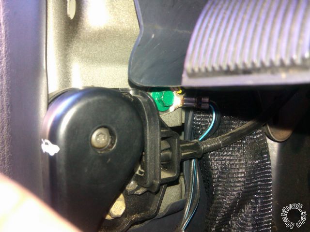
I grounded all my stuff right here. Then i read not to use a factory ground? Some say its ok some say its not? Is this ok? I dont see how making a new ground right next to this into the same metal will make a difference....
viper 5704 / 2004 mountaineer - Page 5 -- posted image.
When in doubt....kick it!
kreg357 
Platinum - Posts: 7,783
Platinum spaceThis member has made a donation to the12volt.com. Click here for more info.spaceThis member has been recognized as an authority in Electrical Theory. Click here for more info.spaceThis member has been recognized as an authority in Mobile Security and Convenience. Click here for more info.spacespace
Joined: January 30, 2009
Location: Pennsylvania, United States
Posted: October 21, 2012 at 8:57 PM / IP Logged  

I solder on a terminal ring to the units' chassis ground wire and try to find a bolt that goes into very solid steel.  The thin metal support brackets that support the dash are not good locations for a ground connection.  Remove the bolt, scrape / wire brush the chassis steel ( removing any paint or rust ) and then re-install the bolt with the terminal ring on it.    That bolt shown with only one wire on it looks OK to me but if you look around you might find another location.

Soldering is fun!
Page of 7

  Printable version Printable version Post ReplyPost New Topic
You cannot post new topics in this forum
You cannot reply to topics in this forum
You cannot delete your posts in this forum
You cannot edit your posts in this forum
You cannot create polls in this forum
You cannot vote in polls in this forum

  •  
Search the12volt.com
Follow the12volt.com Follow the12volt.com on Facebook
Friday, April 26, 2024 • Copyright © 1999-2024 the12volt.com, All Rights Reserved Privacy Policy & Use of Cookies
Disclaimer: *All information on this site ( the12volt.com ) is provided "as is" without any warranty of any kind, either expressed or implied, including but not limited to fitness for a particular use. Any user assumes the entire risk as to the accuracy and use of this information. Please verify all wire colors and diagrams before applying any information.

Secured by Sectigo
the12volt.com spacer
Support the12volt.com
Top
the12volt.com spacer