the12volt.com spacer
icon

timed 12v relay for power folding steps


Post ReplyPost New Topic
< Prev Topic Next Topic >
lvintegra 
Member - Posts: 35
Member spacespace
Joined: December 03, 2012
Location: Texas, United States
Posted: December 03, 2012 at 6:01 PM / IP Logged  

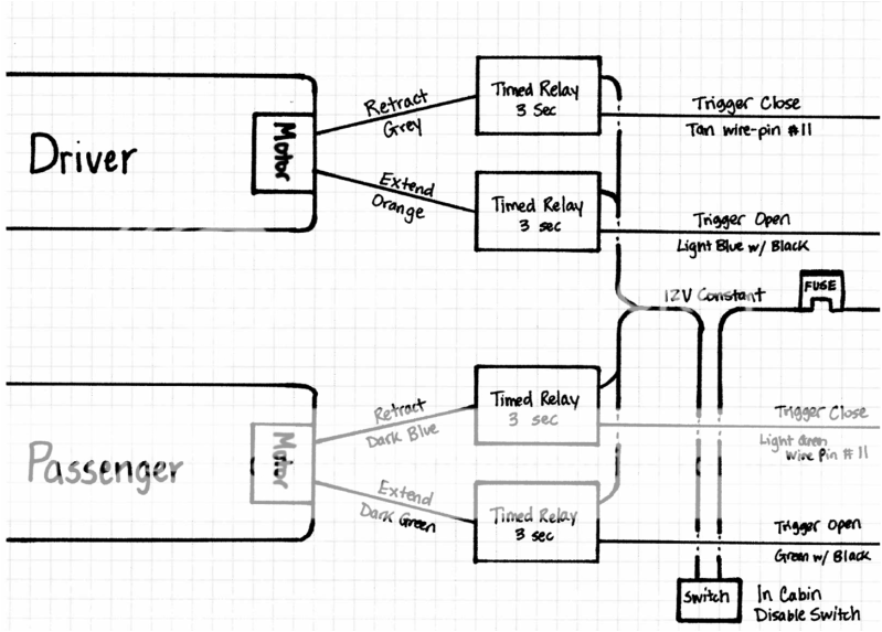
So I want to start with I have little to no experience with relays and making them work for the functions I need them to do oustide just replacing / installing them after somebody else already did all the programming work. I am looking to do a retro fit on some power running boards on my Escalade that did not come with them from the factory. Because mine did not come with them from the factory I have to figure out how to control them myself, rather than the on board computer. One good thing is I know the color wiring diagram for the motors and it's function, as well as the door open / close trigger wires inside the factory harness. So here is my issue, I need to find a relay that can perform the following function:

Must have constant 12V power; once the door open trigger sends the signal to the relay I need the relay to allow 12v power to flow to the motor extension wire for 3 seconds and then stop. *the motors don't have stops therefore if a constant power was applied the motor would continually run even though the step would be fully deployed and eventually burn up*. Inversely, once the door close trigger sends the signal to the relay I need the relay to allow 12v power to flow to the motor retraction wire for 3 seconds and the stop. I have also been advised I should "diode" the relays so the 12v constant doesn't send feedback through the "door open / close trigger wires", not sure what this means exactly.

I put together the following diagram sketch of how I think it could possibly work

[IMG]https://img.photobucket.com/albums/v359/baggedLVintegra/RetrofitPowerRunningBoardSchematic.png[/IMG]

Does anybody have any experience with this type of application and/or timed relay experience and could point me in the right direction of where I could purchase a relay to perform these functions?

Any help is GREATLY appreciated. Thanks - Josh

lvintegra 
Member - Posts: 35
Member spacespace
Joined: December 03, 2012
Location: Texas, United States
Posted: December 03, 2012 at 6:04 PM / IP Logged  
sorry the image embeddment didn't work, here it istimed 12v relay for power folding steps -- posted image.
kreg357 
Platinum - Posts: 7,783
Platinum spaceThis member has made a donation to the12volt.com. Click here for more info.spaceThis member has been recognized as an authority in Electrical Theory. Click here for more info.spaceThis member has been recognized as an authority in Mobile Security and Convenience. Click here for more info.spacespace
Joined: January 30, 2009
Location: Pennsylvania, United States
Posted: December 03, 2012 at 7:37 PM / IP Logged  

Interesting project.  It looks very do-able.  The 3 second driver relay output is the challange.

While it might be possible with some sort of R/C control circuit to give the 3 second timing
another more logical and direct method to accomplish this would be with four 30/40 Amp
relays and 4 PAC TR-7 modules.  Each TR-7 would monitor one door trigger and control one
relay.  The relay wiring would be very simple and you could make up a small enclosure box
for each folding step, one for the right and one for the left.  Here is a link to the PAC-TR7
module.   https://www.the12volt.com/installbay/file.asp?ID=1031

Relay wiring - Pass side:

Relay 1 = Retract
Pin 85 to TR-7 #1 (-) White Output set @ 3 seconds
Pin 86 and 87 to +12V constant fused @ Step motor needs
Pin 30 to Step Motor Dark Blue
Pin 87A not used - insulate

Relay 2 = Extend

Pin 85 to TR-7 #2 (-) Output Output set @ 3 seconds
Pin 86 and 87 to +12V constant fused @ Step motor needs
Pin 30 to Step Motor Dark Green
Pin 87A not used - insulate

Both TR-7's would be programmed as Feature #15, one input pulse gives a 3 second output pulse.

TR-7 #1 Retract
Black to Chassis Ground
Red to +12V thru ON/OFF control switch
Brown to (-) Light Green door close trigger
White to Relay 1 Pin 85

TR-7 #2 Extend

Black to Chassis Ground
Red to +12V thru ON/OFF control switch
Brown to (-) GREEN/ Black door open trigger
White to Relay 2 Pin 85

I imagine there are less expensive ways to do this, so hopefully someone else can jump in with

another idea.

Soldering is fun!
lvintegra 
Member - Posts: 35
Member spacespace
Joined: December 03, 2012
Location: Texas, United States
Posted: December 03, 2012 at 7:43 PM / IP Logged  
So the scenario you lay out above is just for the passenger side only right? So it would need to be doubled and would require (4) total relays and (4) total PAC TR-7s?
lvintegra 
Member - Posts: 35
Member spacespace
Joined: December 03, 2012
Location: Texas, United States
Posted: December 03, 2012 at 7:44 PM / IP Logged  
Sorry just re-read the post and it answered my question, made more sense the third time through :)....so yeah that's a bit pricey, which I don't mind if that is what HAS TO HAPPEN to make it work, but will entertain any ideas
kreg357 
Platinum - Posts: 7,783
Platinum spaceThis member has made a donation to the12volt.com. Click here for more info.spaceThis member has been recognized as an authority in Electrical Theory. Click here for more info.spaceThis member has been recognized as an authority in Mobile Security and Convenience. Click here for more info.spacespace
Joined: January 30, 2009
Location: Pennsylvania, United States
Posted: December 03, 2012 at 7:47 PM / IP Logged  
Yes, that is correct.  One set-up like that for each sides' folding step.  Total cost about $85 with fuses, etc but you can control the relays output to the second.
Soldering is fun!
lvintegra 
Member - Posts: 35
Member spacespace
Joined: December 03, 2012
Location: Texas, United States
Posted: December 03, 2012 at 7:54 PM / IP Logged  
So I'm pretty sure I comprehend your whole scenario and it seems that it would function exactly how I intend, however I am confused by the trigger input / output of the TR-7 being a negative? Wouldn't the door open trigger signal from the vehicle be outputing as a positive? Or am I confused? I have not actually tested to know, but you are much more experienced than I and may possibly already know
kreg357 
Platinum - Posts: 7,783
Platinum spaceThis member has made a donation to the12volt.com. Click here for more info.spaceThis member has been recognized as an authority in Electrical Theory. Click here for more info.spaceThis member has been recognized as an authority in Mobile Security and Convenience. Click here for more info.spacespace
Joined: January 30, 2009
Location: Pennsylvania, United States
Posted: December 03, 2012 at 8:09 PM / IP Logged  
Good point.  You didn't mention the Escalade's year and I just assumed (-), but that is the
beauty of the PAC TR-7.  If you find that it is a (+) trigger you can use the TR-7's Green (+)
Input trigger wire instead of the Brown wire listed above.
Soldering is fun!
lvintegra 
Member - Posts: 35
Member spacespace
Joined: December 03, 2012
Location: Texas, United States
Posted: December 03, 2012 at 8:15 PM / IP Logged  

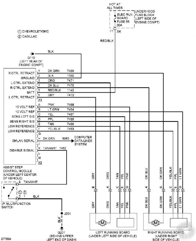
Ok I assumed that was a no biggie, but just trying to grasp everything....I greatly appreciate the help. The Escalade is an 07 BTW, attached is the factory power running board wiring schematic and then also aftermarket AMP power step wiring diagram that shows the trigger wires to tap into for the desired functions.

timed 12v relay for power folding steps -- posted image.

link to amp power steps installation instructions

http://www.amp-research.com/wp-content/uploads/2010/05/download_btn.jpg
lvintegra 
Member - Posts: 35
Member spacespace
Joined: December 03, 2012
Location: Texas, United States
Posted: December 03, 2012 at 8:17 PM / IP Logged  

they need an edit post button lol it won't let me add the pdf but if you go to 07+ Escalade download on this page you can see it http://www.amp-research.com/products/truckaccessories/powerstep/

Page of 8

  Printable version Printable version Post ReplyPost New Topic
You cannot post new topics in this forum
You cannot reply to topics in this forum
You cannot delete your posts in this forum
You cannot edit your posts in this forum
You cannot create polls in this forum
You cannot vote in polls in this forum

  •  
Search the12volt.com
Follow the12volt.com Follow the12volt.com on Facebook
Friday, April 26, 2024 • Copyright © 1999-2024 the12volt.com, All Rights Reserved Privacy Policy & Use of Cookies
Disclaimer: *All information on this site ( the12volt.com ) is provided "as is" without any warranty of any kind, either expressed or implied, including but not limited to fitness for a particular use. Any user assumes the entire risk as to the accuracy and use of this information. Please verify all wire colors and diagrams before applying any information.

Secured by Sectigo
the12volt.com spacer
Support the12volt.com
Top
the12volt.com spacer