the12volt.com spacer
icon

timed 12v relay for power folding steps


Post ReplyPost New Topic
< Prev Topic Next Topic >
lvintegra 
Member - Posts: 35
Member spacespace
Joined: December 03, 2012
Location: Texas, United States
Posted: December 04, 2012 at 12:51 PM / IP Logged  

KPierson wrote:
What are you planning on using for the "trigger open" and "trigger close"? I read you mention the door pin, but most vehicles only have one door pin.

According to the aftermarket AMP step instructions,

"Locate wire loom in door sill. Carefully remove wire wrap and find the trigger wire.

Drivers side: LIGHT BLUE wire with BLACK STRIPE

Passenger side: GREEN wire with BLACK STRIPE.

Locate the brown plug and using supplied Posi-Tap™ connector, splice into trigger wire.

2007-2008 Vehicles:

Drivers side: TAN wire- pin #11 Passengers side: LIGHT GREEN wire-pin#11"

So it suggest taping 2 wires per side, which would trigger Driver Open / Driver Close ; Pass Open / Pass Close....and the AMP steps work like Factory Equipped in that either door open on each side opens that side step.

lvintegra 
Member - Posts: 35
Member spacespace
Joined: December 03, 2012
Location: Texas, United States
Posted: December 04, 2012 at 12:58 PM / IP Logged  

Just found this by doing a forum search for 07 Escalade wiring

Door Trigger see notes - see notes
Notes: The LF door is gray/black at the DDM, brown 16 pin plug, pin 13. The RF door is BLACK/ white at the PDM, brown 16 pin plug, pin 13. The LR door is lt. blue/black at the BCM, pink plug, pin 15. The RR door is lt. GREEN/ black at the BCM, pink plug, pin 14. Use all four wires and diode isolate each.
The DDM (Driver Door Module) is in the driver door.
The PDM (Passenger Door Module) is in the passenger door.
The BCM (Body Control Module) is to the left of the steering column.

lvintegra 
Member - Posts: 35
Member spacespace
Joined: December 03, 2012
Location: Texas, United States
Posted: December 04, 2012 at 1:22 PM / IP Logged  

The more I research and the more I read I reveal more....it appears to me that in the AMP instructions, and another brand Bestop, both say to tap the same 4 wires. I believe these 4 are Front Dr Trigger, Rear Dr Trigger, Front Pass Trigger, Rear Pass Trigger.

After reading this statement from Bestop

To test if the black controller (460.91), wire harness, motor and lights work, hook up to battery and touch any of the 4 door trigger wires to ground. The board for that side should go down and the lights should turn on. The board should go up and the lights should turn off when the wire is removed from ground. Note that a 2-second delay before the PowerStep returns to the stowed/retracted position.

I believe the controllers don't have a "door close trigger" rather once it loses the "door open trigger" it automatically reverses polarity 2 seconds later and retracts the step

KPierson 
Platinum - Posts: 3,527
Platinum spaceThis member consistently provides reliable informationspace
Joined: April 14, 2005
Location: Ohio, United States
Posted: December 04, 2012 at 2:02 PM / IP Logged  
OK, that makes much more sense now. So the step is long enough for back passengers to climb in and out?
What do other people with these steps do for a controller?
Kevin Pierson
lvintegra 
Member - Posts: 35
Member spacespace
Joined: December 03, 2012
Location: Texas, United States
Posted: December 04, 2012 at 2:10 PM / IP Logged  

KPierson wrote:
OK, that makes much more sense now. So the step is long enough for back passengers to climb in and out?
What do other people with these steps do for a controller?

Yes the steps are long enough for back passengers as well.

Others either have the powered boards from the factory (BCM / Computer Controlled) or they have fixed running boards. To date,with all my research on numerous forums, nobody has successfully retrofit these before, so this is the first.

I have determined that for sure without a doubt these can be installed to work just like factory functionality, it's just a matter of two options:

1) "Design" a Controller module using timed relays and PAC TR-7 modules, plotting a wiring scheme, soldering diodes, running all the wires and testing it. Should work but not 100% confirmed without doing it all. Estimated cost $110 for all parts, LABOR intensive

2) Buy the AMP Power Step Control Module and Wiring Harness - Estimated cost $200, cleaner install NO design work

So the catch, the only issue with #2 is after talking to AMP Tech Support their module is programmed to run the motor for 5 seconds (the time it takes to extend / retract the AMP steps) but from my calculations it only takes 2-3 seconds tops for the OEM steps to reach full extend / full retract. Meaning the motors would run for 2 full seconds after the arms were maxed out. I'm concerned this 2 seconds of continued power to the motors will wear the motors out much sooner than they should.

lvintegra 
Member - Posts: 35
Member spacespace
Joined: December 03, 2012
Location: Texas, United States
Posted: December 04, 2012 at 2:18 PM / IP Logged  

so after comparing these two videos on youtube, there is no way the AMP steps are 5 seconds, they appear faster than OEM

[url]http://www.youtube.com/watch?v=tAHPMU0naig[/url]

this video at 1:17

[url]http://www.youtube.com/watch?v=PM7MvTKtRkg[/url]

KPierson 
Platinum - Posts: 3,527
Platinum spaceThis member consistently provides reliable informationspace
Joined: April 14, 2005
Location: Ohio, United States
Posted: December 04, 2012 at 3:34 PM / IP Logged  
They probably run the motors a hair on the longer side as opposed to the shorter side. As the motors age they'll slow down. Running them for an extra 2 seconds forward and backwards most likely won't shorten the life too much and that way they won't have to worry about issues with the steps not fully extending five years down the road.
Kevin Pierson
KPierson 
Platinum - Posts: 3,527
Platinum spaceThis member consistently provides reliable informationspace
Joined: April 14, 2005
Location: Ohio, United States
Posted: December 04, 2012 at 9:49 PM / IP Logged  
In reality, a microcontroller based design would be the most elegant approach. You could have two (-) inputs (one for front door, one for back), two outputs to drive relays, and a potentiometer that adjusts the outputs from 0-10 seconds.
If you are interested, I could put something together as long as you agree to cover my actual out of pocket hardware costs (I'll do the programming for free). I would guess the cost would be under $50 with relays and relay harnesses but if you are seriously interested I can work up an exact number. I would build you two separate modules - one per side. Each would have their own enclosure and Molex wire harness and two relays. The relays would be standard Bosch style relays in stackable harnesses.
Let me know if you are interested - I will build and test both modules and provide pictures before taking any payment from you. If for some reason they don't work I'll even take them back and refund your money - I'm just trying to help you out and keep myself busy!
Kevin Pierson
lvintegra 
Member - Posts: 35
Member spacespace
Joined: December 03, 2012
Location: Texas, United States
Posted: December 05, 2012 at 8:25 AM / IP Logged  
PM sent....sounds like a plan, I think we can make this work.
KPierson 
Platinum - Posts: 3,527
Platinum spaceThis member consistently provides reliable informationspace
Joined: April 14, 2005
Location: Ohio, United States
Posted: December 05, 2012 at 10:27 PM / IP Logged  
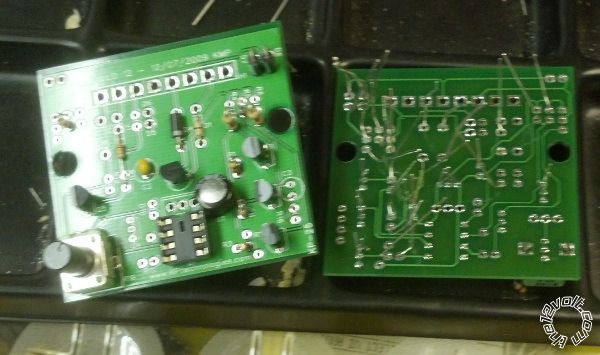
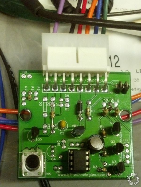
I messed around with this today. I wrote the code this morning and after I got the kids to bed tonight I put the hardware together. Not bad progress for 24 hours. My initial testing shows that it works perfect. The output is adjustable from 0-~10 seconds through the potentiometer. Pretty straightforward project!
timed 12v relay for power folding steps - Page 3 -- posted image.
Kevin Pierson
Page of 8

  Printable version Printable version Post ReplyPost New Topic
You cannot post new topics in this forum
You cannot reply to topics in this forum
You cannot delete your posts in this forum
You cannot edit your posts in this forum
You cannot create polls in this forum
You cannot vote in polls in this forum

  •  
Search the12volt.com
Follow the12volt.com Follow the12volt.com on Facebook
Friday, May 2, 2025 • Copyright © 1999-2025 the12volt.com, All Rights Reserved Privacy Policy & Use of Cookies
Disclaimer: *All information on this site ( the12volt.com ) is provided "as is" without any warranty of any kind, either expressed or implied, including but not limited to fitness for a particular use. Any user assumes the entire risk as to the accuracy and use of this information. Please verify all wire colors and diagrams before applying any information.

Secured by Sectigo
the12volt.com spacer
Support the12volt.com
Top
the12volt.com spacer