the12volt.com spacer
icon

timed 12v relay for power folding steps


Post ReplyPost New Topic
< Prev Topic Next Topic >
lvintegra 
Member - Posts: 35
Member spacespace
Joined: December 03, 2012
Location: Texas, United States
Posted: December 06, 2012 at 3:24 PM / IP Logged  
Yeah I'm just going to wait, have a full schedule this weekend anyway so I'll just postpone the wiring until I have everything ready. Planned to loom everything anyway but I agree solder is the way to go!
lvintegra 
Member - Posts: 35
Member spacespace
Joined: December 03, 2012
Location: Texas, United States
Posted: December 06, 2012 at 4:12 PM / IP Logged  
and actually the T-Taps are ONLY for the taps into the door wiring inside the door panel, nothing else
howie ll 
Pot Metal - Posts: 16,466
Pot Metal spacespace
Joined: January 09, 2007
Location: United Kingdom
Posted: December 06, 2012 at 4:43 PM / IP Logged  
Shoving them inside the door panel is almost as bad as the engine bay, vibration damp and corrosion without the heat, just wait for two weeks of door slamming.
DON'T EVER USE THEM.
KPierson 
Platinum - Posts: 3,527
Platinum spaceThis member consistently provides reliable informationspace
Joined: April 14, 2005
Location: Ohio, United States
Posted: December 07, 2012 at 8:41 PM / IP Logged  
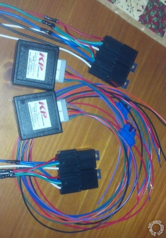
timed 12v relay for power folding steps - Page 6 -- posted image.
Finished this project up tonight!
Kevin Pierson
lvintegra 
Member - Posts: 35
Member spacespace
Joined: December 03, 2012
Location: Texas, United States
Posted: December 08, 2012 at 10:35 AM / IP Logged  
Sweeeeet! Shoot me a PM with payment info and we can get it all taken care of. Thanks again!
lvintegra 
Member - Posts: 35
Member spacespace
Joined: December 03, 2012
Location: Texas, United States
Posted: December 10, 2012 at 9:01 AM / IP Logged  

So I have a concern, which is NOT verified yet, but I thought I'd gauge insight on a potential problem. I physically got the running boards / motors in my hands last night. I briefly tried to run 12v power and ground off the battery to the motor to test the reverse polarity theory and I got nothing. No combination of 2 wires gave power to the motor. I know 100% they work as the seller sent video of them in operation and I don't question his integrity one bit. Looking at the wiring diagram on Page 1 of this thread, it appears (for the drivers side) that:

There are 2 wires coming off the motor (Grey and Orange) and 3 wires "off to the side of the motor" (Tan Yellow Pink)

On the actual motors there is just a bundle of 5 wires coming out of the same location on the motor (Black Red Yellow Green and Orange)

My initial assumption, atleast beause of the diagram, was that the Grey / Orange wires controlled the motor and the Tan / Yellow / Pink were tied to a safety sensor for the steps. Now I'm starting to think that the factory step controller provided power to the motor whilst monitoring the "saftety sensor" and therefore straight power to the Grey / Orange would not trigger the motor.

Do you guys think I may have to jump the 3 wires intended for the safety sensor for it to realize it can operate? If so how should I go about accomplishing this? In the diagram these wires are labeled as "Low Reference" "Sens Left Sig" and "10 Volt Ref" respectively.

KPierson 
Platinum - Posts: 3,527
Platinum spaceThis member consistently provides reliable informationspace
Joined: April 14, 2005
Location: Ohio, United States
Posted: December 10, 2012 at 10:02 AM / IP Logged  
I would try grounding the low reference and putting 10vdc on the 10 volt ref and see what happens. I would assume that the sensor is inside the steps and that the sensor is sending something back to the controller. I would guess that there is some sort of interlock in the steps that if the sensor becomes inoperable the steps won't move.
To get your 10 volts you can use a 7810 voltage regulator or a 7812 regulator feeding a voltage divider? 10 volts is a weird voltage to work with in a car. You may even try hooking a 9vdc battery up to it just for testing (make sure you connect the ground of the battery to the car or to your power supply so that both systems share a ground).
If you can get the steps to work you can start playing with the parameters that make it work - ie will it work on a 5vdc or does it have to be 10vdc? The closer you can get to 5 the better off you'll be.
Kevin Pierson
lvintegra 
Member - Posts: 35
Member spacespace
Joined: December 03, 2012
Location: Texas, United States
Posted: December 10, 2012 at 10:52 AM / IP Logged  

So:

-normal 12v and ground to the 2 "motor" wires

-ground the "low reference" wire

-apply 10v power to the "10 Volt Ref" via the 7810 voltage regulator

-but what about the last wire "Sens Sig Left"?

2 issues arise with this....1) the wiring diagram I have does not match the colors of the actual wires coming out of the motor, so I can't readily identify which ones do what. I have a feeling getting my hands on the right wiring schematic would be tough. 2) I've never used a "voltage regulator" nor do I know where to get one locally, would probably have to order online or something

KPierson 
Platinum - Posts: 3,527
Platinum spaceThis member consistently provides reliable informationspace
Joined: April 14, 2005
Location: Ohio, United States
Posted: December 10, 2012 at 11:35 AM / IP Logged  
I would ignore the sensor wire at this point. I believe it is an output, not an input. Not having the correct wiring diagram may make it a bit more difficult to figure out which wire does what.
I have never used a 7810 either, I am only assuming they make them. You would have to order one, from some place like Mouser.com or Digikey.com. They are very simple devices, apply voltage in that is at least one volt higher then desired voltage out, ground the ground pin, and then use your voltage out pin as desired. They are 3 pin transistor type devices. Like I said, I would start with a 9vdc battery and see if it works with a 9vdc. A 7809 may be easier to find then a 7810. A 7805 (5vdc regulator) is in stock at RadioShack which is why I said the closer you can get to 5vdc and have the system working the better off you are.
Kevin Pierson
lvintegra 
Member - Posts: 35
Member spacespace
Joined: December 03, 2012
Location: Texas, United States
Posted: December 10, 2012 at 11:53 AM / IP Logged  
so miraculously I have a Cadillac techs number from another forum who we've bought and sold parts from and I texted him to see if he could help with the diagram and he has an Escalade on his lift right now with the factory installed power running boards and is going to map over the wires across the connector for me. Atleast I'll know each wires function now. The rest seems to be the more difficult part. Hopefully I can do the 9v battery trick tonight and give it a try
Page of 8

  Printable version Printable version Post ReplyPost New Topic
You cannot post new topics in this forum
You cannot reply to topics in this forum
You cannot delete your posts in this forum
You cannot edit your posts in this forum
You cannot create polls in this forum
You cannot vote in polls in this forum

  •  
Search the12volt.com
Follow the12volt.com Follow the12volt.com on Facebook
Friday, May 2, 2025 • Copyright © 1999-2025 the12volt.com, All Rights Reserved Privacy Policy & Use of Cookies
Disclaimer: *All information on this site ( the12volt.com ) is provided "as is" without any warranty of any kind, either expressed or implied, including but not limited to fitness for a particular use. Any user assumes the entire risk as to the accuracy and use of this information. Please verify all wire colors and diagrams before applying any information.

Secured by Sectigo
the12volt.com spacer
Support the12volt.com
Top
the12volt.com spacer