the12volt.com spacer
icon

timed 12v relay for power folding steps


Post ReplyPost New Topic
< Prev Topic Next Topic >
lvintegra 
Member - Posts: 35
Member spacespace
Joined: December 03, 2012
Location: Texas, United States
Posted: December 10, 2012 at 1:15 PM / IP Logged  

So I got my hands on the specific 07 power running boards wiring schematic, but it is extremely difficult to read (due to scan / fax) so I won't upload it. The routing of the wires is all similar to the other I posted but some have different titles:

Both sides "2 motor power wires" are the same, it's the 3 sensor wires that are different (this just talking driver side):

Original Schematic - Tan "Low Reference"  ; 07 Specific Schematic - Tan "Running Board Motor Halt Sensor Left Return"

Original Schematic - Yellow "Sens Left Sig" ; 07 Specific Schematic - Yellow "Running Board Motor Halt Sensor Left Signal"

Original Schematic - Pink "10 Volt Ref" ; 07 Specific Schematic - Pink "Running Board Motor Halt Sensor Left Reference"

The 07 specific schematic does not call out any of the wires being 10v specifically, although I find it hard to believe in 07 they used the controller one way with a 12v reference to the signal and later changed it to a 10v reference for the signal.

Does any of this new information change your proposed plan? Would using 12v to the reverse wire instead of 10v do any damage?

KPierson 
Platinum - Posts: 3,527
Platinum spaceThis member consistently provides reliable informationspace
Joined: April 14, 2005
Location: Ohio, United States
Posted: December 10, 2012 at 3:58 PM / IP Logged  
I would guess that there is an encoder in the motor that sends 10vdc pulses back to the controller. The controller then looks for the pulses to stop to know when the sill is completely in or out (ie motor stall condition). It's possible that the system would work at battery voltage, but I would start low and work your way high. Is there anything you can take apart on the motor to check out the wiring? There may something as simple as a relay interlocking the motor wiring to the sensor power wires.
Kevin Pierson
lvintegra 
Member - Posts: 35
Member spacespace
Joined: December 03, 2012
Location: Texas, United States
Posted: December 10, 2012 at 4:25 PM / IP Logged  
I've been thinking about that today (pulling the motor apart), I may just do that tonight if I get the time and its feasible.
lvintegra 
Member - Posts: 35
Member spacespace
Joined: December 03, 2012
Location: Texas, United States
Posted: December 10, 2012 at 10:54 PM / IP Logged  

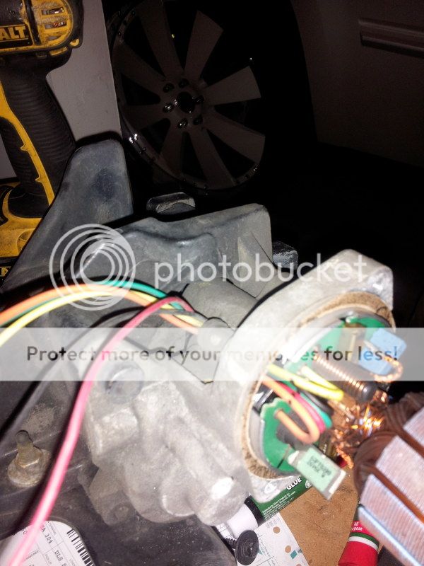
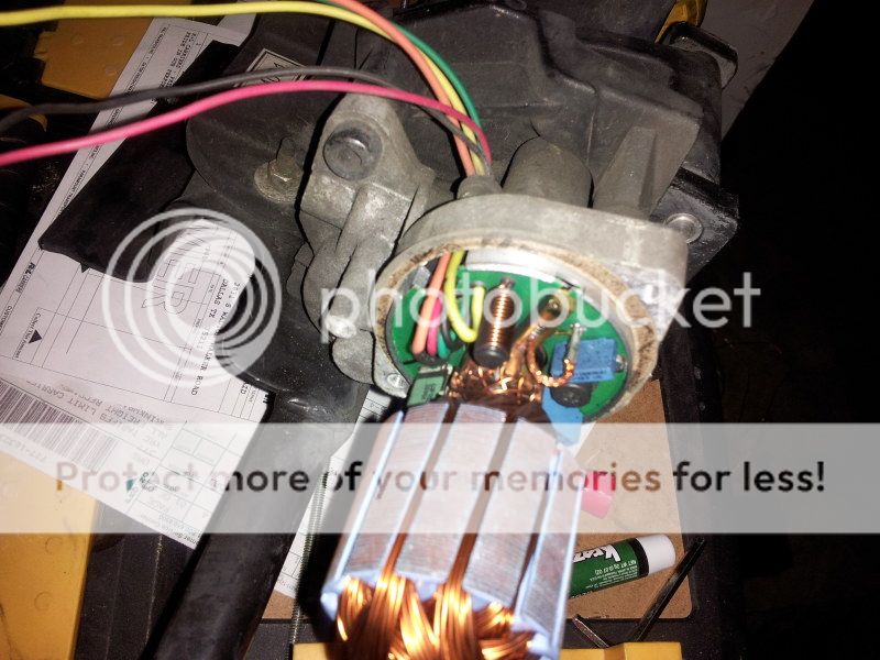
so I took apart the motor and this is what I found inside

timed 12v relay for power folding steps - Page 7 -- posted image.

timed 12v relay for power folding steps - Page 7 -- posted image.

it doesn't appear to be any kind of relay that I can tell, the wires just go straight into the board.

I attempted to wire it up as you suggested earlier except for I didn't have a 9v battery so I just briefly touched the "10v ref" to the 12v battery post with a very very small wire and it began working as it should. The wire got pretty tacky to the post quick so I quickly pulled it off.

But now I know for sure what wires do what, how to bypass the safety sensor although I have to figure out how to make it constant. Do you suggest just running the ground of the "safety sensor" to the rest of the grounds permanently and branching off my already ran 12v power regulating it down directly to the "10v ref" permanently?

KPierson 
Platinum - Posts: 3,527
Platinum spaceThis member consistently provides reliable informationspace
Joined: April 14, 2005
Location: Ohio, United States
Posted: December 11, 2012 at 10:49 AM / IP Logged  
Do you have an ammeter? I would be interested to know how much current the 10v source draws.
Also, the little blue things look like they might be relays, any chance of getting better pictures or part numbers off of them?
I have an electronics warehouse near me, I'll see if I can find a 7810 or 7809 in stock locally.
Kevin Pierson
lvintegra 
Member - Posts: 35
Member spacespace
Joined: December 03, 2012
Location: Texas, United States
Posted: December 11, 2012 at 10:53 AM / IP Logged  
Don't have an ammeter unfortunately....I could probably take the motor case back off tonight and get better pics / P/Ns off those relays tonight. Anything other info you might possibly need while I'm in there?....also have the Modules shipped?
lvintegra 
Member - Posts: 35
Member spacespace
Joined: December 03, 2012
Location: Texas, United States
Posted: December 11, 2012 at 5:52 PM / IP Logged  

So I picked up a 9v battery on the way home and re-tested it as layed out previously and it still worked well.

I couldn't get a close enough picture of the "blue things" to read the print but it looked like this:

6103311829521

^ 1 "a backwards 4" K63U6

lvintegra 
Member - Posts: 35
Member spacespace
Joined: December 03, 2012
Location: Texas, United States
Posted: December 14, 2012 at 11:10 AM / IP Logged  
Hey Kevin your inbox is full so my last PM didn't go through......my plan was to branch off the 12v constant power off the battery that I already ran down by the step motors as the input to the regulator, ground the center pin and output to the motor sensor. It would be a constant regulated power. Is that a bad idea?
KPierson 
Platinum - Posts: 3,527
Platinum spaceThis member consistently provides reliable informationspace
Joined: April 14, 2005
Location: Ohio, United States
Posted: December 14, 2012 at 11:23 AM / IP Logged  
Sorry about that, it is cleaned out now.
The effectiveness of that setup depends on how much current the sensor uses. If it pulls a couple mA it won't be a problem. If it is latching a relay at ~150mA it will drain your battery after a few days of sitting.
A more efficient way to run the sensor would be to power it right off the +12vdc output of each relay. You'll need to diode isolate each output to prevent backfeeding and fuse blowing. Wire two separate 1A diodes directly to each relay output (pin 30 on both relays) with the stripe closest to the regulator. Connect the striped sides of the diodes together and use that point as the feed for the regulator. This way, the regulator will only be on when the steps need to move.
Kevin Pierson
lvintegra 
Member - Posts: 35
Member spacespace
Joined: December 03, 2012
Location: Texas, United States
Posted: December 14, 2012 at 1:16 PM / IP Logged  
This confuses me with regards to the :+12vdc output of each relay. There are 2 wires that control the motor, it was my impression that 1 one would come out of 2 relays and hook to the 2 motor wires. In that case they would have to be able to reverse polarity to make the motor extened / retract and therefore neither would ever be constant output +12vdc.  So how would I hook up the 12v power to the regulator if neither was constant power?
Page of 8

  Printable version Printable version Post ReplyPost New Topic
You cannot post new topics in this forum
You cannot reply to topics in this forum
You cannot delete your posts in this forum
You cannot edit your posts in this forum
You cannot create polls in this forum
You cannot vote in polls in this forum

  •  
Search the12volt.com
Follow the12volt.com Follow the12volt.com on Facebook
Friday, May 2, 2025 • Copyright © 1999-2025 the12volt.com, All Rights Reserved Privacy Policy & Use of Cookies
Disclaimer: *All information on this site ( the12volt.com ) is provided "as is" without any warranty of any kind, either expressed or implied, including but not limited to fitness for a particular use. Any user assumes the entire risk as to the accuracy and use of this information. Please verify all wire colors and diagrams before applying any information.

Secured by Sectigo
the12volt.com spacer
Support the12volt.com
Top
the12volt.com spacer