the12volt.com spacer
icon

icbm7071 alarm in 2004 f150


Post ReplyPost New Topic
< Prev Topic Next Topic >
antman1 
Copper - Posts: 121
Copper spacespace
Joined: February 13, 2012
Location: Tennessee, United States
Posted: January 08, 2013 at 10:40 AM / IP Logged  
ok. here is what I got so far from 2003 F150 wiring and I redid the last info I had from offroadzj when he helped me on my Chrysler Town and Country.
5 Pin Heavy Gauge Harness:
Red - Battery Constant 12v+ Positive Wire (+): Yellow and Light GREEN/ Purple
Purple - Starter Positive Wire (+): RED / Light Blue
Orange - Accessory Positive Wire (+): Gray / YELLOW   
Pink A - Ignition Positive Wire (+): Dark Blue/Light Green
Pink B - Second Ignition Positive Wire (+): RED / Black
*You will need to use a relay to power the 2nd accessory. Just a standard 30a/40a automotive relay connected as follows:
Pin 85 - Blue/White (-) bypass wire in H4 harness
Pin 86 - Orange Accessory wire from above
Pin 87 - 12v Constant Fused (can tie into fused Red 12v constant above)
Pin 30 - BLACK/ White (+) Second Accessory Positive Wire (+): BLACK/ Light Green    
7 Pin Secondary (H4) Harness:
1-3 - Factory wiring to R/S module
4 - Blue/White (See Above)
5 - Gray/Black - N/C
6 - BLACK/ White - Chassis Ground
7 - Violet/White - Tachometer Wire Negative Wire (-): The tach wire on the 4.2L engine is a dark blue/light green at the coil pack
10 Pin Primary (H1) Harness
1 - Brown - To Siren (+) input
2 - White - Parking Light Positive Wire (+): Brown
3 - Violet - N/C
4 - Blue/Black - Power Door Unlock Negative Wire (-): Pink/Light Green
5 - BROWN / Black - Chassis Ground
6 - Violet/Black - N/C
7 - GREEN/ Black - Power Door Lock Negative Wire (-): Pink / YELLOW
8 - WHITE/ Black - Chassis Ground
9 - Red - 12v Constant fused (can tie into heavy gauge red wire from main harness)
10 - Black - Chassis Ground
6 Pin Secondary (H2) Harness:
1 - Orange - Starter kill relay input
*If you wish to enable the starter kill, you will need to cut the factory Starter Positive Wire (+): RED / Light Blue wire at the ignition switch and you will need another relay (same as above) connected as follows:
Pin 85 - Orange Ground when running (H2-1)
Pin 86 - Ignition (+) (Pink from main harness)
Pin 87a - ignition side of cut starter wire
Pin 30 - Vehicle side of cut starter wire
*Connect the remote start output (Purple) between the relay and the car!
Pin 87 - N/C
2 - Blue - N/C
3 - WHITE/ Black - N/C
4 - PURPLE / Black - N/C
5 - BLACK/ White - Domelight Supervision Wire (+): BLACK/ Light Blue (Requires Relay)
6 - RED / White - N/C
8 Pin (H3) Harness:
1 - GREEN/ Black -
2 - GREEN / WHITE - See Above
3 - Red - N/C
4 - Gray - Must add aftermarket hood pin.
5 - Brown - Brake Light Positive Wire (+): Light Green
6 - Yellow - Pink wire from main harness
7 - Green - ?
8 - Purple - N/C
Not sure I have it all right but hoping someone else can look at it and tell me what they think.
antman1 
Copper - Posts: 121
Copper spacespace
Joined: February 13, 2012
Location: Tennessee, United States
Posted: January 09, 2013 at 10:41 AM / IP Logged  
Did a few corrections.
*You will need to use a relay to power the 2nd accessory. Just a standard 30a/40a automotive relay connected as follows:
Pin 85 - Blue/White (-) bypass wire in H4 harness
Pin 86 - Orange Accessory wire from above
Pin 87 - 12v Constant Fused (can tie into fused Red 12v constant above)
Pin 30 - Second Accessory Positive Wire (+): BLACK/ Light Green     
10 Pin Primary (H1) Harness
2 - White - Parking Light Positive Wire (+): Brown (set polarity jumper to + on alarm)
8 Pin (H3) Harness:
1 - GREEN/ Black - dk. GREEN/ purple     -     driver kick panel
2 - GREEN / WHITE - arms on lock w/door open   
7 - Green - blk/yel (L) or blk/pnk (R)     -     each door harness
Does all of this look right? Only things I am not sure about is if I need any more relays or diodes or resistors for these connections. Also the factory arm and disarm stuff is confusing me. The factory key fob has a panic button but I dont think it has an alarm.
And is the bypass module going to wire into this somehow?
Sorry for all the questions. just want to make sure I am doing it right.
antman1 
Copper - Posts: 121
Copper spacespace
Joined: February 13, 2012
Location: Tennessee, United States
Posted: January 10, 2013 at 7:28 PM / IP Logged  
Anyone able to help me on this? I just don't want to do this wrong.
kreg357 
Platinum - Posts: 7,781
Platinum spaceThis member has made a donation to the12volt.com. Click here for more info.spaceThis member has been recognized as an authority in Electrical Theory. Click here for more info.spaceThis member has been recognized as an authority in Mobile Security and Convenience. Click here for more info.spacespace
Joined: January 30, 2009
Location: Pennsylvania, United States
Posted: January 10, 2013 at 8:56 PM / IP Logged  

Have you done a quick check to verify that the F150's ignition wires match-up with the 2003 model year

and not the 2004 model?  There are big differences so it should be easy to tell.

Assuming that the wiring matches a 2003 F150, all your connections look Ok.

 
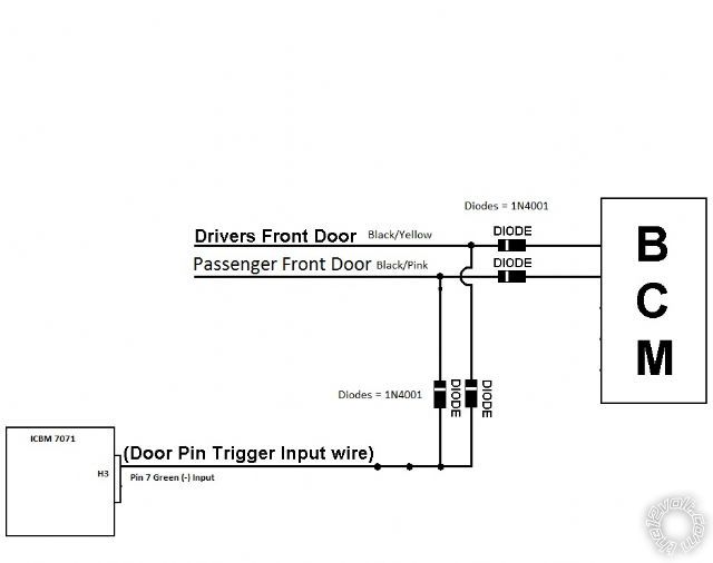
You will need 2 diodes ( 1N4001) to isolate the two door trigger connection to the Green (-) Door Trigger
Input wire ( bands towards the R/S ).

Think I would connect the Red +12V input wire from the relay pack to one of the trucks +12V constant

wire (Yellow ) and the ACC2 relay power and the other Red power wire ( w/15Amp fuse ) to the other +12V
constant wire ( GREEN/ Purple ) to split the load up.

The door lock wiring and connections are good if the truck came with Factory Keyless Entry.

One minor typo :

Pin 85 - Orange Ground when running (H2-1)     Should be Ground When Armed
Pin 86 - Ignition (+) (Pink from main harness)
Pin 87a - ignition side of cut starter wire
Pin 30 - Vehicle side of cut starter wire
*Connect the remote start output (Purple) between the relay and the car!

Soldering is fun!
antman1 
Copper - Posts: 121
Copper spacespace
Joined: February 13, 2012
Location: Tennessee, United States
Posted: January 11, 2013 at 8:00 AM / IP Logged  
Thank you.
I compared the wiring diagrams for 2004 and 2003 f150 models and they are mostly the same. I am thinking about not installing the starter kill relay in this one because it has the PATS system anyway.
As for the diodes I am not sure what you mean on the green door trigger. Are you talking about
8 Pin (H3) Harness:
7 - Green - blk/yel (L) or blk/pnk (R)     -     each door harness
not sure on that connection.
Also were would the 1100F connect to the alarm?
kreg357 
Platinum - Posts: 7,781
Platinum spaceThis member has made a donation to the12volt.com. Click here for more info.spaceThis member has been recognized as an authority in Electrical Theory. Click here for more info.spaceThis member has been recognized as an authority in Mobile Security and Convenience. Click here for more info.spacespace
Joined: January 30, 2009
Location: Pennsylvania, United States
Posted: January 11, 2013 at 9:29 AM / IP Logged  

1100F connections

Red +12V to ICBM 7071 Red @ 10 Pin Plug
Black Chassis Ground to ICBM 7071 Black @ 10 Pin Plug
Blue/White (-) 200mA Bypass Output to ICBM 7071 Blue/White (-) 200 mA Bypass Output @ 7 Pin Plug

Door Trigger :

icbm7071 alarm in 2004 f150 - Page 2 -- posted image.

Soldering is fun!
antman1 
Copper - Posts: 121
Copper spacespace
Joined: February 13, 2012
Location: Tennessee, United States
Posted: January 11, 2013 at 2:02 PM / IP Logged  
Ok that diagram helps a lot. Thank you. So I will use 4 diodes total. I will have to separate the wires in the truck wire and place a diode in place on the drivers side wiring and passenger side wiring and also use diodes on the wires I have coming from Pin 7 Green.
I ordered some more supplies from ebay and I am waiting on the 1100F to come in then I will do my prep work and try to make it all pretty. I'll let you know if I have anymore questions. Thank you a lot for your help.
antman1 
Copper - Posts: 121
Copper spacespace
Joined: February 13, 2012
Location: Tennessee, United States
Posted: January 11, 2013 at 2:49 PM / IP Logged  
got another question. I know this requires a relay, how would I connect the relay?
6 Pin Secondary (H2) Harness:
Pin 87 - N/C
5 - BLACK/ White - Domelight Supervision Wire (+): BLACK/ Light Blue (Requires Relay)
Pin 85 - BLACK/ White (H2-5)
Pin 86 - ?
Pin 87a - ?
Pin 30 - ?
Pin 87 - ?
Sorry am drawing a blank on this.
kreg357 
Platinum - Posts: 7,781
Platinum spaceThis member has made a donation to the12volt.com. Click here for more info.spaceThis member has been recognized as an authority in Electrical Theory. Click here for more info.spaceThis member has been recognized as an authority in Mobile Security and Convenience. Click here for more info.spacespace
Joined: January 30, 2009
Location: Pennsylvania, United States
Posted: January 12, 2013 at 3:19 PM / IP Logged  
2003 F150    DOMELIGHT SUPERVISION   BLACK/ LIGHT BLUE (+)    IN PASSNEGER KICK PANEL
Extra 30/40 Amp SPDT relay to convert ICBM 7071 (-) output to (+) output for F150
Pin 85 - To ICBM 7071  BLACK/ White (H2-5) (-) 200mA Domelight Supervision Output
Pin 86 & Pin 87     +12V constant  thru 5 Amp fuse
Pin 87a - Not Used
Pin 30 - F150    BLACK/ LIGHT BLUE (+)    IN PASSNEGER KICK PANEL
Soldering is fun!
antman1 
Copper - Posts: 121
Copper spacespace
Joined: February 13, 2012
Location: Tennessee, United States
Posted: January 12, 2013 at 4:40 PM / IP Logged  
Thank you a lot. I think I have all the notes I need and I have cleaned them up a lot now and think I have it all set. Here is what I got if you wanna check it out: icbm7071-f150-install-notes.pdf
On the last relay for the 5amp fuse I am out of inline fuse holders. I am thinking I will solder direct to the 5amp fuse for pin 86 & 87.
I cant wait to get all my stuff I am waiting on to get this done.
Page of 4

  Printable version Printable version Post ReplyPost New Topic
You cannot post new topics in this forum
You cannot reply to topics in this forum
You cannot delete your posts in this forum
You cannot edit your posts in this forum
You cannot create polls in this forum
You cannot vote in polls in this forum

  •  
Search the12volt.com
Follow the12volt.com Follow the12volt.com on Facebook
Thursday, March 28, 2024 • Copyright © 1999-2024 the12volt.com, All Rights Reserved Privacy Policy & Use of Cookies
Disclaimer: *All information on this site ( the12volt.com ) is provided "as is" without any warranty of any kind, either expressed or implied, including but not limited to fitness for a particular use. Any user assumes the entire risk as to the accuracy and use of this information. Please verify all wire colors and diagrams before applying any information.

Secured by Sectigo
the12volt.com spacer
Support the12volt.com
Top
the12volt.com spacer