the12volt.com spacer
icon

icbm7071 alarm in 2004 f150


Post ReplyPost New Topic
< Prev Topic Next Topic >
antman1 
Copper - Posts: 121
Copper spacespace
Joined: February 13, 2012
Location: Tennessee, United States
Posted: February 01, 2013 at 3:57 PM / IP Logged  
antman1 wrote:
kreg357 wrote:

The Directed 1100F is pretty much the same install as the ADS TB FM2.  Here is a link to it's install guide :

http://cdnprotected2.idatalink.com/corporate/Content/Manuals/TB-FM2/ADS-TB-FM2-EN_20130104.pdf?nvb=20130201205250&nva=20130201215250&hash=09bafb0d87bf9f3617b48
It gives the transponder connector diagram, connector location and wire colors you need.

Are the truck's wires matching up with the 2003 or 2004 F150?  It is sometimes easier to get the lock wires

in the passenger kick panel.

Thank you, I got everything except Domelight supervisor wire (wasnt sure how to check if I found the right wire in the passenger kick panel. had a black with light blue strip wire but I didnt get any voltage with the door open or close on it. Domelight Supervision isnt really needed though.
The PDF that you just referenced said I have a type 1-C connector located on the PATS harness. do you know about were to look for that harness? Also it said for that bypass module not to connect the Ignition wire to the connector at the PATS plug but to connect it to the vehicles ignition. Do I need to wire it there or the PATS Plug for the 1100F?
Forgot to metion they are matching 2003 f150 so far.
kreg357 
Platinum - Posts: 7,783
Platinum spaceThis member has made a donation to the12volt.com. Click here for more info.spaceThis member has been recognized as an authority in Electrical Theory. Click here for more info.spaceThis member has been recognized as an authority in Mobile Security and Convenience. Click here for more info.spacespace
Joined: January 30, 2009
Location: Pennsylvania, United States
Posted: February 01, 2013 at 4:40 PM / IP Logged  

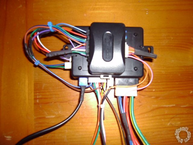
I usually connect the 1100F Pink Ignition wire to the R/S's ( ICBM7071 in your case ) thick Ignition1 Output wire.  It goes to the vehicles Ignition1 wire.

Here is a photo of an iDatalink bypass module ( similar to the 1100F ) mated to a R/S brain.  You can see the ADS Pink Ignition wire going to the R/S's thick blue Ignition1 Output wire :

icbm7071 alarm in 2004 f150 - Page 4 -- posted image.

As for the transponder connector, it originates at the ignition switch.  The connector you are looking for is located about 8" down the steering column from the ignition switch.  ( As long as the transponder is the same as the 2003 model...)

Domelight Supervision isn't mandatory...

Soldering is fun!
antman1 
Copper - Posts: 121
Copper spacespace
Joined: February 13, 2012
Location: Tennessee, United States
Posted: February 01, 2013 at 6:01 PM / IP Logged  
Thank you for the help. I have to say, I think the difficulty level of finding these wires was more than my Chrysler Town and Country. lol. I got most all of it completed and the alarm is working fine but I have to connect the Ignition wire and TX, RX wires tomorrow. I have been working at this for 10 hours and I am bushed. tomorrow I will have to make everything pretty and connect those wires. I tried the remote start with the key in the ignition and it turned on and turned off after 5 seconds. I think I have the wrong wire connected at the fuel injector. there is a red wire and a white wire. I connected it to the white wire and it may have a stripe on it too.
Were do you normally connect the Tach wire?
kreg357 
Platinum - Posts: 7,783
Platinum spaceThis member has made a donation to the12volt.com. Click here for more info.spaceThis member has been recognized as an authority in Electrical Theory. Click here for more info.spaceThis member has been recognized as an authority in Mobile Security and Convenience. Click here for more info.spacespace
Joined: January 30, 2009
Location: Pennsylvania, United States
Posted: February 01, 2013 at 6:11 PM / IP Logged  

Each F.I. should have two wires.  Compare several F.I.'s.  All should have one common colored wire.  The other wire color is unique for each F.I. and that is the one you want to use.  You can test / verify with a Digital Multi Meter.  Set to 20 V AC, Red test lead on suspect wire, Black Test lead on chassis ground ( negative battery terminal ).  With engine running, DMM should read between 1 and 6 volts at idle and increase with RPM's.

Follow the 1100F install guide.  Start with a Factory Reset, then Step 1 ( Install Mode ) two-blinks and then Step 2A ( hopefully Type 1C ).

Soldering is fun!
antman1 
Copper - Posts: 121
Copper spacespace
Joined: February 13, 2012
Location: Tennessee, United States
Posted: February 02, 2013 at 2:09 PM / IP Logged  
got it all installed and up in the dash. before I programmed the 1100F I tried to remote start and it never would fire up the engine only turned over. I programmed it and it fired up and ran for 5 to 6 seconds then off again. So I went back to looking for my tach wire. I tried my multimeter and it doesn't have 20 V AC setting. It had a 200 ACV and 500 ACV setting. I tried those and it said 30 and was staying the same even when revving the engine. I tried both wires on the coil pack and injector.
antman1 
Copper - Posts: 121
Copper spacespace
Joined: February 13, 2012
Location: Tennessee, United States
Posted: February 02, 2013 at 3:07 PM / IP Logged  
got it. the tach wire is now connected to GREEN / WHITE on the coil pack on the left side of the 4.6l engine. Alarm and remote start are working great. Thank you for all your help!
Some notes on this, lock and unlock wires I had to get from the passenger side up high in the dash. and also the passenger door trigger wire too. but I am glad it is done. :) Thank you again. Couldn't have done it right w/out your help.
kreg357 
Platinum - Posts: 7,783
Platinum spaceThis member has made a donation to the12volt.com. Click here for more info.spaceThis member has been recognized as an authority in Electrical Theory. Click here for more info.spaceThis member has been recognized as an authority in Mobile Security and Convenience. Click here for more info.spacespace
Joined: January 30, 2009
Location: Pennsylvania, United States
Posted: February 02, 2013 at 3:37 PM / IP Logged  
Good deal!  icbm7071 alarm in 2004 f150 - Page 4 -- posted image.  Glad it's all set and working for you.  Plenty of cold weather left.
Soldering is fun!
Page of 4

Sorry, you can NOT post a reply.
This topic is closed.

  Printable version Printable version Post ReplyPost New Topic
You cannot post new topics in this forum
You cannot reply to topics in this forum
You cannot delete your posts in this forum
You cannot edit your posts in this forum
You cannot create polls in this forum
You cannot vote in polls in this forum

  •  
Search the12volt.com
Follow the12volt.com Follow the12volt.com on Facebook
Wednesday, April 24, 2024 • Copyright © 1999-2024 the12volt.com, All Rights Reserved Privacy Policy & Use of Cookies
Disclaimer: *All information on this site ( the12volt.com ) is provided "as is" without any warranty of any kind, either expressed or implied, including but not limited to fitness for a particular use. Any user assumes the entire risk as to the accuracy and use of this information. Please verify all wire colors and diagrams before applying any information.

Secured by Sectigo
the12volt.com spacer
Support the12volt.com
Top
the12volt.com spacer