


overhead flip down monitor
Home /
the12volt's Install Bay /
Mobile Video, GPS, and Navigation / overhead flip down monitor ( Topic Closed)


Posted: February 20, 2013 at 12:14 AM / IP Logged

Posted: February 21, 2013 at 9:57 PM / IP Logged
Posted: February 22, 2013 at 11:20 PM / IP Logged

Posted: February 23, 2013 at 5:59 AM / IP Logged
Posted: February 23, 2013 at 7:30 AM / IP Logged
Posted: February 23, 2013 at 9:01 AM / IP Logged
Posted: February 23, 2013 at 9:18 AM / IP Logged
Posted: February 23, 2013 at 4:31 PM / IP Logged
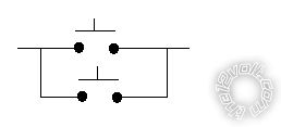 Hence you can push either (or both) and it simply mimics how the original switch behaves.
There is no need to involve the unit's power since the unit's circuitry handles that.
Nor is there any need for relays - unless as a solution for very long extended wires and interference etc. Depending on the circuitry, it's possible that the new extended wires cause problems (by injecting noise) but that should be solved with a small capacitor (0.01uF etc), but that can be added later only if needed.
You'll need to solder the new wires to the abovementioned solder points. That has an element of risk - not only the usual thermal & solder damage etc, but also electrical damage to sensitive components thru static etc depending on the circuit. That can be minimised by following normal static handling procedures - ie, grounded soldering iron and unit etc. And (obviously?) with the unit unpowered and disconnected from the vehicle etc.
Actually, I'd suggest extending via a plug and socket for easy removal. Maybe a small 2.5mm or 3.5mm panel socket somewhere on the unit's enclosure, and your switch to the suitable plug?
Hence you can push either (or both) and it simply mimics how the original switch behaves.
There is no need to involve the unit's power since the unit's circuitry handles that.
Nor is there any need for relays - unless as a solution for very long extended wires and interference etc. Depending on the circuitry, it's possible that the new extended wires cause problems (by injecting noise) but that should be solved with a small capacitor (0.01uF etc), but that can be added later only if needed.
You'll need to solder the new wires to the abovementioned solder points. That has an element of risk - not only the usual thermal & solder damage etc, but also electrical damage to sensitive components thru static etc depending on the circuit. That can be minimised by following normal static handling procedures - ie, grounded soldering iron and unit etc. And (obviously?) with the unit unpowered and disconnected from the vehicle etc.
Actually, I'd suggest extending via a plug and socket for easy removal. Maybe a small 2.5mm or 3.5mm panel socket somewhere on the unit's enclosure, and your switch to the suitable plug?Posted: February 24, 2013 at 10:37 AM / IP Logged
Posted: February 24, 2013 at 4:56 PM / IP Logged
 Printable version
| You cannot post new topics in this forum You cannot reply to topics in this forum You cannot delete your posts in this forum You cannot edit your posts in this forum You cannot create polls in this forum You cannot vote in polls in this forum |

| Search the12volt.com |
Follow the12volt.com 
Saturday, March 21, 2026 • Copyright © 1999-2026 the12volt.com, All Rights Reserved • Privacy Policy & Use of Cookies

Saturday, March 21, 2026 • Copyright © 1999-2026 the12volt.com, All Rights Reserved • Privacy Policy & Use of Cookies
Disclaimer:
*All information on this site ( the12volt.com ) is provided "as is" without any warranty of any kind, either expressed or implied, including but not limited to fitness for a particular use. Any user assumes the entire risk as to the accuracy and use of this information. Please
verify all wire colors and diagrams before applying any information.
