the12volt.com spacer
icon

2001-2003 F-150 Remote Start w/Keyless Pictorial


Post ReplyPost New Topic
< Prev Topic Next Topic >
jared26 
Member - Posts: 17
Member spacespace
Joined: December 26, 2015
Location: British Columbia, Canada
Posted: December 29, 2015 at 6:46 AM / IP Logged  
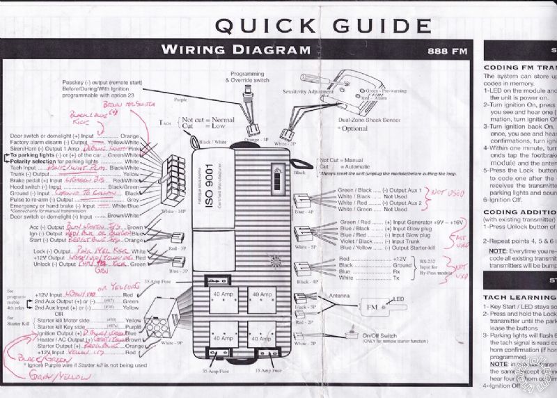
2001-2003 F-150 Remote Start w/Keyless Pictorial - Page 4 -- posted image.
Looks like the last link didn't work so here it is.
Thanks!
kreg357 
Platinum - Posts: 7,783
Platinum spaceThis member has made a donation to the12volt.com. Click here for more info.spaceThis member has been recognized as an authority in Electrical Theory. Click here for more info.spaceThis member has been recognized as an authority in Mobile Security and Convenience. Click here for more info.spacespace
Joined: January 30, 2009
Location: Pennsylvania, United States
Posted: December 29, 2015 at 6:08 PM / IP Logged  

OK. To power the extra ignition wires you will need two 30/40 Amp SPDT relays and the 5 pin harness plus an in-line fuse

holder with 20 Amp fuses and a couple of 1N4007 diodes.  Wire as follows :

Relay 1 for IGN2 :

Relay Pin 85 to R/S IGN (-) Output Blue wire
Relay pins 86 and 87 to +12V constant through 20 Amp fuse
Relay Pin 30 to F150 RED / Black wire in ignition harness

Relay 2 for ACC2 :

Relay Pin 85 to R/S ACC (-) Output Brown wire
Relay pins 86 and 87 to +12V constant through 20 Amp fuse
Relay Pin 30 to F150 BLACK/ Light Green wire in ignition harness

Connect the diodes across each relay, pins 86 and 85, with the diodes band towards pin 86.

There are ample +12V constant wires at the main ignition plug to individually power each circuit.

Soldering is fun!
jared26 
Member - Posts: 17
Member spacespace
Joined: December 26, 2015
Location: British Columbia, Canada
Posted: December 29, 2015 at 7:03 PM / IP Logged  
Thanks again for your help. Do I have to add those relays in because there aren't enough outputs on this unit or was there another reason? Just asking out of curiosity as I'm new to all this.
Thanks
jared26 
Member - Posts: 17
Member spacespace
Joined: December 26, 2015
Location: British Columbia, Canada
Posted: December 29, 2015 at 7:09 PM / IP Logged  
Oh, I see I should have read more carefully, thats to power the - outputs from the red 3 pin plug, I see what you're saying now.
Thank you
kreg357 
Platinum - Posts: 7,783
Platinum spaceThis member has made a donation to the12volt.com. Click here for more info.spaceThis member has been recognized as an authority in Electrical Theory. Click here for more info.spaceThis member has been recognized as an authority in Mobile Security and Convenience. Click here for more info.spacespace
Joined: January 30, 2009
Location: Pennsylvania, United States
Posted: December 29, 2015 at 9:07 PM / IP Logged  
Yes.  The truck has many ignition wires that need to be powered during a remote start.  The R/S unit has the capability to power some of them but not all.  These vehicle circuits are designed / engineered to be separate circuits so they can't be tied together and powered by one R/S output.  The R/S does have low current (-) ignition outputs that can be used to energize relays that in turn can supply high current (+) outputs for these vehicle circuits.  Extra work but necessary to properly remote start the engine.
Soldering is fun!
jared26 
Member - Posts: 17
Member spacespace
Joined: December 26, 2015
Location: British Columbia, Canada
Posted: December 29, 2015 at 9:15 PM / IP Logged  
I gotcha, that poses another question then, the R/S has a programmable 4th relay that I can set from acc +/- ign +/- or start +/- could I use that for one of them and just add one additional relay from one of the low current outputs to the ignition wiring?
kreg357 
Platinum - Posts: 7,783
Platinum spaceThis member has made a donation to the12volt.com. Click here for more info.spaceThis member has been recognized as an authority in Electrical Theory. Click here for more info.spaceThis member has been recognized as an authority in Mobile Security and Convenience. Click here for more info.spacespace
Joined: January 30, 2009
Location: Pennsylvania, United States
Posted: December 30, 2015 at 3:54 AM / IP Logged  
Didn't see that on the diagram but yes, if it is a high current selectable ignition type output, use the 4th relay ( flex output ) in lieu of an external relay.
Soldering is fun!
jared26 
Member - Posts: 17
Member spacespace
Joined: December 26, 2015
Location: British Columbia, Canada
Posted: December 30, 2015 at 3:58 AM / IP Logged  
Thanks Kreg, I appreciate all your help, I'll try to wrap it up in the next few days and I'll let you know how it went.
jared26 
Member - Posts: 17
Member spacespace
Joined: December 26, 2015
Location: British Columbia, Canada
Posted: December 30, 2015 at 6:49 PM / IP Logged  
So here's an odd update, this morning when I was waiting for the truck to warm up I set the R/S into tach learning mode, it went through its sequence to confirm that it did learn and then when I got to work this morning and shut the truck off it kept running. In the end I had to unplug the 9 pin main harness at the R/S to get the truck to shut off so now I'm going to have to figure out whats going on there.
rheckbert3 
Member - Posts: 28
Member spacespace
Joined: November 25, 2013
Location: Massachusetts, United States
Posted: December 30, 2015 at 6:54 PM / IP Logged  
jared26 wrote:
So here's an odd update, this morning when I was waiting for the truck to warm up I set the R/S into tach learning mode, it went through its sequence to confirm that it did learn and then when I got to work this morning and shut the truck off it kept running. In the end I had to unplug the 9 pin main harness at the R/S to get the truck to shut off so now I'm going to have to figure out whats going on there.
Is your brake safety interrupt wire connected? The remote start system should have "shut down" after you put the key in the truck and pressed the brake pedal to shift into gear.
Ricky
Page of 7

  Printable version Printable version Post ReplyPost New Topic
You cannot post new topics in this forum
You cannot reply to topics in this forum
You cannot delete your posts in this forum
You cannot edit your posts in this forum
You cannot create polls in this forum
You cannot vote in polls in this forum

  •  
Search the12volt.com
Follow the12volt.com Follow the12volt.com on Facebook
Friday, April 26, 2024 • Copyright © 1999-2024 the12volt.com, All Rights Reserved Privacy Policy & Use of Cookies
Disclaimer: *All information on this site ( the12volt.com ) is provided "as is" without any warranty of any kind, either expressed or implied, including but not limited to fitness for a particular use. Any user assumes the entire risk as to the accuracy and use of this information. Please verify all wire colors and diagrams before applying any information.

Secured by Sectigo
the12volt.com spacer
Support the12volt.com
Top
the12volt.com spacer