the12volt.com spacer
icon

4206p 00 malibu guide?


Post ReplyPost New Topic
< Prev Topic Next Topic >
weaz4200 
Member - Posts: 27
Member spacespace
Joined: November 15, 2013
Location: Illinois, United States
Posted: November 17, 2013 at 10:32 PM / IP Logged  
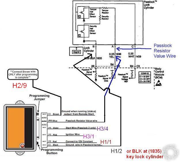
Final wiring on PLJX...
4206p 00 malibu guide? - Page 3 -- posted image.
kreg357 
Platinum - Posts: 7,789
Platinum spaceThis member has made a donation to the12volt.com. Click here for more info.spaceThis member has been recognized as an authority in Electrical Theory. Click here for more info.spaceThis member has been recognized as an authority in Mobile Security and Convenience. Click here for more info.spacespace
Joined: January 30, 2009
Location: Pennsylvania, United States
Posted: November 18, 2013 at 5:40 AM / IP Logged  
Probably better to use the ground at the key cylinder, being as it is used as a reference for the Passlock2 voltage.  Always best to follow the install diagram.     
Soldering is fun!
weaz4200 
Member - Posts: 27
Member spacespace
Joined: November 15, 2013
Location: Illinois, United States
Posted: November 18, 2013 at 3:29 PM / IP Logged  
Will do.
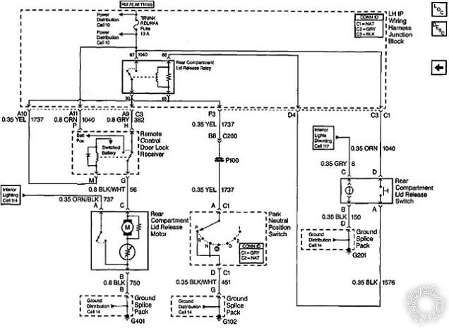
Was hoping you could help me understand the trunk release diagram...
The relay will be wired as you stated...
** The Trunk Release Output is (-) and the Malibu needs a (+) signal. Use a 30/40 Amp SPDT relay w/ 10 Amp fuse
as shown below :
Relay Pin 85 to H2/5
Relay Pin 86 & 87 to +12V constant through 10 Amp fuse (((H1/1   RED     (+)12VDC CONSTANT INPUT (Red @ ignswitch) (C2/PIN A) )))
Relay Pin 30 to Malibu BLACK/ WHITE (+) @ TRUNK RELEASE SWITCH
Relay Pin 87a not used
So looking at the diagram.
Theres 12V+ at the 87 and 86 pin of the Rear Compartment Lid release relay.
The splice at 1040 goes all the way through the Lid release switch on the right comes around to the 86 pin on the Lid release relay. The coil between 86/85 only gets energized when the Park neutral position switch is in Park or Neutral. So once the Lid release Relay coil is energized the switch portion on the release relay closes and 12V+ flows through 87 to 30 and then down to the Remote Control Door Lock Reciever.
ORG 1040 has 12V+ and "M" is getting ground from G102 after the Park Neutral Position switch.
Then I'm stuck. How does the rest of the circuit work?
4206p 00 malibu guide? - Page 3 -- posted image.
kreg357 
Platinum - Posts: 7,789
Platinum spaceThis member has made a donation to the12volt.com. Click here for more info.spaceThis member has been recognized as an authority in Electrical Theory. Click here for more info.spaceThis member has been recognized as an authority in Mobile Security and Convenience. Click here for more info.spacespace
Joined: January 30, 2009
Location: Pennsylvania, United States
Posted: November 18, 2013 at 7:02 PM / IP Logged  
I believe that the Remote Control Door Lock Receiver is the part of the Factory RKE system.  You have a Factory FOB
that has a Trunk Release button on it.  The "relay" shown in the Remote Control Door Lock Receiver is normally in
the position shown and pressing the Rear Compartment Lid Release Switch ( with the trans in Park or Neutral ) will
get +12V to the Rear Compartment Lid Release Motor.  What is not shown is that when you press the Factory FOB
Trunk Release button that "relay" will energize ( if trans is in Park or Neutral ) and supply +12V to the Rear Compartment
Lid Release Motor.
Soldering is fun!
weaz4200 
Member - Posts: 27
Member spacespace
Joined: November 15, 2013
Location: Illinois, United States
Posted: November 18, 2013 at 7:31 PM / IP Logged  
I see. Thanks.
So what I need to do with the Relay I get is wire PIN 30 and splice into the BLK/WHT wire (circuit 56) between the Remote control door lock reciever and the Lid release motor. Correct?
weaz4200 
Member - Posts: 27
Member spacespace
Joined: November 15, 2013
Location: Illinois, United States
Posted: November 18, 2013 at 7:45 PM / IP Logged  
Or black wire right after the Lid release switch (1576) since if I was to wire in at BLK/WHT (56) then there would be a possibility that I could accidentally pop the trunk regardless of PRNDL switch position.
weaz4200 
Member - Posts: 27
Member spacespace
Joined: November 15, 2013
Location: Illinois, United States
Posted: November 21, 2013 at 12:24 PM / IP Logged  
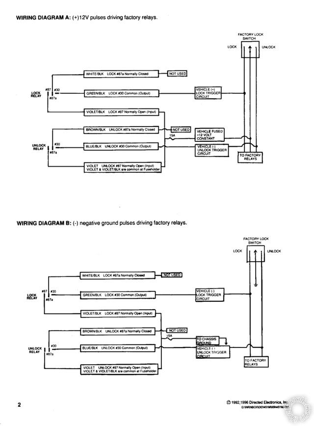
Finally received the 451M and the Passlock module. I'm looking at the 451M diagram and I'm uncertain.
Looks like I'm not using the WHITE/ black and the BROWN / black wires...
1) Does the 3 pin plug on the 451M get plugged into the python module?
2) How do I distinguish, from the Malibu's door lock schematic whether I use Dia A or Dia B?
Thanks,
ROB
4206p 00 malibu guide? - Page 3 -- posted image.
kreg357 
Platinum - Posts: 7,789
Platinum spaceThis member has made a donation to the12volt.com. Click here for more info.spaceThis member has been recognized as an authority in Electrical Theory. Click here for more info.spaceThis member has been recognized as an authority in Mobile Security and Convenience. Click here for more info.spacespace
Joined: January 30, 2009
Location: Pennsylvania, United States
Posted: November 21, 2013 at 8:19 PM / IP Logged  

There appears to be differences between the Bulldog Security and Audiovox wire guides ( not unusual ).  One

says BLACK/ White and the other says Black for the Trunk Release wire at the switch.  Your wire diagrams also
says Black.  That will probably be the correct answer, but as per S.O.P., use a DMM to verify.  So the updated
relay wiring will probably be like this :
Relay Pin 85 to H2/5
Relay Pin 86 & 87 to +12V constant through 10 Amp fuse (((H1/1   RED     (+)12VDC CONSTANT INPUT (Red @ ignswitch) (C2/PIN A) )))
Relay Pin 30 to Malibu BLACK (+) @ TRUNK RELEASE SWITCH
Relay Pin 87a not used

On the 451M, you will plug it right into the Python 4206 door lock port.  The correct diagram is the Type A.  Yes,

the WHITE/ Black and BROWN / Black wires will not be used.  Additionally, you can connect the Violet fused wire to any
convenient +12V constant source ( that can handle 15 Amps ).

Soldering is fun!
weaz4200 
Member - Posts: 27
Member spacespace
Joined: November 15, 2013
Location: Illinois, United States
Posted: November 21, 2013 at 9:27 PM / IP Logged  
I will definitely be using my DVOM...
I guess I'm down to my final questions on the wiring.
Seeing as I will be running all the 12+ constants through the (red@ignition) (c2/PIN A)... That's not gonna be a problem? Like too much on that one circuit? This includes the Violet fused wire as well.
Also, are there any other wires I need to add fuses to?
I know you stated 10 Amp fuse for the Relay Pin 86 & 87 for trunk release so I still have to pick up a fuse holder and wire it up with the relay.
BUT
The wiring for the PLJX is not fused on the 12+ constant. Should I add a fuse to it?
THANKS VERY MUCH,
ROB
kreg357 
Platinum - Posts: 7,789
Platinum spaceThis member has made a donation to the12volt.com. Click here for more info.spaceThis member has been recognized as an authority in Electrical Theory. Click here for more info.spaceThis member has been recognized as an authority in Mobile Security and Convenience. Click here for more info.spacespace
Joined: January 30, 2009
Location: Pennsylvania, United States
Posted: November 21, 2013 at 10:02 PM / IP Logged  
I believe you will find two +12V constant power wires in the Malibu's main ignition harness, one Red and the other
RED / Black perhaps.  You can split the load up between these two wires.  The PLJX bypass module draws very little
current and really doesn't need a fuse.  It is OK to connect its' power wire to one of the Pythons's thick +12V constant
wires ( like H1/1 ) after the fuse.
Soldering is fun!
Page of 5

  Printable version Printable version Post ReplyPost New Topic
You cannot post new topics in this forum
You cannot reply to topics in this forum
You cannot delete your posts in this forum
You cannot edit your posts in this forum
You cannot create polls in this forum
You cannot vote in polls in this forum

  •  
Search the12volt.com
Follow the12volt.com Follow the12volt.com on Facebook
Thursday, May 23, 2024 • Copyright © 1999-2024 the12volt.com, All Rights Reserved Privacy Policy & Use of Cookies
Disclaimer: *All information on this site ( the12volt.com ) is provided "as is" without any warranty of any kind, either expressed or implied, including but not limited to fitness for a particular use. Any user assumes the entire risk as to the accuracy and use of this information. Please verify all wire colors and diagrams before applying any information.

Secured by Sectigo
the12volt.com spacer
Support the12volt.com
Top
the12volt.com spacer