the12volt.com spacer
icon

dball2, viper 2010 nissan maxima


Post ReplyPost New Topic
< Prev Topic Next Topic >
magnamagus 
Member - Posts: 19
Member spacespace
Joined: January 23, 2014
Location: Arizona, United States
Posted: February 02, 2014 at 12:59 AM / IP Logged Link to Post Post Reply Quote magnamagus
I am hooking up a Viper remote start/security DBALL2 Bypass using Data to Data Mode--- 2010 Nissan Maxima PUSH TO START
Alarm: VIPER 5706 -- SUPPORTS DATA TO DATA -- REMOTE START + Security
DBALL2 BYPASS INSTALL GUIDE: http://www.xpresskit.com/VehicleCompatibility.aspx?p=null&year=2010&make=Infiniti&model=G37%20%28Smart%20Key%29&ps=1&s=0&c=0
Can someone verify the WIRE TO WIRE Cconnections FROM THE STANDARD VIPER MAIN HARNESS & REMOTE START HARNESS To the vehicle used in any Dball D2D connections.
1. Which wires from the. standard VIPER Alarm/Remote start Harnesses (6 pin, 3 pin, 10 pin,) Needed to be connected to the VEHICLE in DATA-TO-DATA MODE?
2. IN data to data mode, IF ANY, which WIRE TO WIRE connections will have to be made from the VIPER ALARM/REMOTE START TO THE VEHICLE in Data-to-data mode?
3. Of the connectors that need to be connected to the vehicle, which connectors require Relays or Diodes?
STANDARD VIPER ALARM HARNESS CONNECTORS INCLUDED WITH ALARM (6 pin, 3 pin, 10 pin)
MAIN HARNESS, 6 PIN CONNECTOR
--H1/1 Red (+) 12vDC Constant -----> Does this go to Ignition harness?? or Not?
--H1/2 Black (-) chassis ground -----> Connect to vehicle factory bolt?? Or NOT?
--H1/3 Brown (+) Siren -----> Connect to Siren - + and – to chassis
--H1/4 WHITE/ Brown Parking light isolation wire –---> Not used - D2D
--H1/5 White Parking light output – (+ or -) depending on jumper –---> NOT used - D2D
--H1/6 Orange (-) 500mA Ground w? armed output – starter kill circuit – uses relay –--> NOT USED
Door Lock, 3 PIN CONNECTOR 
--1 Blue (-) 500mA Unlock output -----> Data to data
--2 Empty
--3 Green (-) 500mA lock output ------> Data to daa
REMOTE START, 10 PIN HEAVY GAUGE 
---H3/1 Pink (+) ignition 1 input/ouput --->
---H3/2 RED / White (+) fused (30a) ignition 2 / Flex relay INPUT 87 ---->
---H3/3 Orange (+) ACCESSORY output --------> ignition harness??
---H3/4 Violet (+) STARTER OUTPUT (car side) [onboard relay – direct connect] -----> Brake Switch (+)
---H3/5 Green (+) STARTER INPUT (key side) [onboard relay- direct connect] -----> ?
---H3/6 Red (+) fused (30a) IGNITION 1 INPUT ---->
---H3/7 Pink/White (+) IGNITION 2 / Flex relay OUTPUT ----> Where????
---H3/8 Pink/Black (+) Flex relay INPUT 87a key side (if required) of Flex relay ---------> WHERE???
---H3/9 RED / Black (+) fused (30a) ACCESSORY / starter input (POLARITY FEED FOR Accessory/starter input relay) ---------> 12v constant ignition harness??
---H3/10 ---> No connection ??
[H3/2 RED / WHITE, H3/6 RED, H3/9 RED / BLACK and H1/1 RED are connected to 12v constant]
Erick
freqsounds 
Copper - Posts: 289
Copper spacespace
Joined: October 17, 2008
Location: Virginia, United States
Posted: February 03, 2014 at 8:46 PM / IP Logged Link to Post Post Reply Quote freqsounds
The only wires to connect in D2D mode are in black. The blue dashed lines are for W2W and are not needed. The lock, unlock, and ignition wires are the only ones that need to be connected in D2D from the Viper. Everything else goes through the databus of the DBALL2.
No diodes are needed, but if it's a manual transmission, you will need the two relays depicted in the instructions.
No question is stupid or not worth asking. You were once a noob, right? :)
magnamagus 
Member - Posts: 19
Member spacespace
Joined: January 23, 2014
Location: Arizona, United States
Posted: February 04, 2014 at 1:46 PM / IP Logged Link to Post Post Reply Quote magnamagus
Question:
1. In regards to the "Stater Interrupt", are the (H5)Starter INPUT and (H4) Starter OUTPUT, really necessary OR is this handle by DBALL2 through through it's Starter 1 and Ignition 1 connections???
---H3/4 Violet (+)Â STARTER OUTPUT (car side)
---H3/5 Green (+)Â STARTER INPUT (key side)
2. The 2010 Nissan Maxima has TWO starters and Ignitions: (-) Starters 1 and (-)Starter 2, and, (+)Ignitions 1 and (-) Ignition. Now, the Dball2 Install Guide, says to connect from the DBALL2 only Ignition Input(+) [to Dball2 ignition input & output] and Starter 1 (+) out put [to Brake Wire (+)]?    Is this correct? And, does the Dball2 handle the Ignition & Starting sequence entirely through these wires?
Again, thank you for your assistance...
Erick
freqsounds 
Copper - Posts: 289
Copper spacespace
Joined: October 17, 2008
Location: Virginia, United States
Posted: February 04, 2014 at 4:24 PM / IP Logged Link to Post Post Reply Quote freqsounds
The starter wires aren't used. But you'll need the Ignition 1 input wire from the H3 harness.
When using the DBALL/DBALL2, nevermind the car wiring diagram. Only follow the instructions in the DBALL/DBALL2 installation instructions.
Are you installing W2W or D2D? You can't do both. The starter wires on both the remote start and DBALL are used only in W2W mode. If you have the DBALL firmware loaded, there's no point in using W2W -- it's extra work. D2D allows both units to 'talk' to each other. The DBALL is the middle man that 'talks' to your car as well. Because it can 'talk' to your car, it eliminates a LOT of wires in D2D mode. In W2W, all the wires are required because it has no way to 'talk' to the remote start. So connecting all the wires allows the DBALL to 'monitor' instead of 'talk', allowing it to know what both systems are doing at the same time when using W2W.
So, again, if you're using D2D mode, only use the wires in black. If you're using W2W, the blue-dashed wires need to be connected IN ADDITION TO the black wires. If you're using D2D, disregard the blue-dashed wires.
I hope this helps clear up your questions a bit! If you have any other questions, please describe the mode you are using (W2W or D2D).
No question is stupid or not worth asking. You were once a noob, right? :)
magnamagus 
Member - Posts: 19
Member spacespace
Joined: January 23, 2014
Location: Arizona, United States
Posted: February 05, 2014 at 7:08 AM / IP Logged Link to Post Post Reply Quote magnamagus
D2D - data to data mode will be used to connect the alarm.
Questions: You stated I will need the "Ignition 1 input wire from the H3 harness". I have located H3/1 and H3/6 (below).
---H3/1 Pink (+) ignition 1 input/ouput
---H3/6 Red (+) fused (30a) IGNITION 1 INPUT
1. Do I need to connect the 10 gauge "H3/6 Red fused" to a 12v constant source and then the "H3/1 Pink ignition input/output wire" to the 24 gauge Dball2 "ignition status input/output wires"?
dball2, viper 2010 nissan maxima -- posted image.
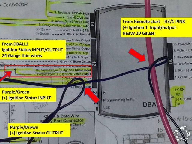
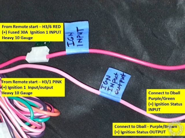
2. I was intending to connect the remote start's heavy 10 gauge "H3/1`Pink Ignition Input/Output" wire TO the DBALL2 24 gauge "Ignition Status Input" and "Ignition status output" wire per the Dball2 install manual (photo). Is this correct?
Photo below: The 'large Red arrows' show were wires are supposed to intersect (dball2 manual). This indicate were I intend to military splice the DBALL2 ignition output(PURPLE / brown) to the ignition input (PURPLE / green) as indicated in the dball2 install diagram. I then intended to military splice the 24 gauge ignition input (PURPLE / green) to the 10 gauge "H3/1 Pink Ignition input/out" wire from the remote start.   
2a. Are these connections correct? This seems odd connecting a 24 gauge wire (dball) to a 10 gauge wire (remote start)?
dball2, viper 2010 nissan maxima -- posted image.
Erick
freqsounds 
Copper - Posts: 289
Copper spacespace
Joined: October 17, 2008
Location: Virginia, United States
Posted: February 05, 2014 at 7:47 AM / IP Logged Link to Post Post Reply Quote freqsounds
1. Yes, that'll be connected to 12V constant (+)
2. Yes, those connections are correct.
No question is stupid or not worth asking. You were once a noob, right? :)
magnamagus 
Member - Posts: 19
Member spacespace
Joined: January 23, 2014
Location: Arizona, United States
Posted: February 06, 2014 at 3:59 AM / IP Logged Link to Post Post Reply Quote magnamagus
In regards to your answer:
Therefore, I will connect the remote start's heavy 10 gauge "H3/1`Pink Ignition Input/Output" wire TO the DBALL2's two 24 gauge "Ignition Status Input" and "Ignition status output" wire in the following manner. I will military splice two wires from the DBALL2, these are 24 gauge Ignition output(PURPLE / brown) to the Ignition Input (PURPLE / green) as indicated in the install diagram. Then, I will military splice the 24 gauge ignition input (PURPLE / green) to the 10 gauge "H3/1 Pink Ignition input/out" wire from the 5706 remote start.
Question 1: After the above connections are made to the heavy 10 gauge "H3/1`Pink Ignition Input/Output", does the PINK H3/1 wire need to be connected anywhere else (to the vehicle perhaps) OR is that the final connection i.e. Remote start to Dball2?
Question 2: Is it a good idea to use a diode 1N4001 1N4001, 1N4007 at the BCM for (-) lock & (-)unlock wires to protect the BCM. For example, inserting a diode leg (diode stripe towards the R/S) into the BCM empty pin holes for Lock and Unlock. The diodes leg diameter is the correct size to make solid contact with the BCM connector inside. This will protect the BCM?
Again, thank you for your assistance... Greatly appreciated...
Erick
freqsounds 
Copper - Posts: 289
Copper spacespace
Joined: October 17, 2008
Location: Virginia, United States
Posted: February 06, 2014 at 6:41 AM / IP Logged Link to Post Post Reply Quote freqsounds
Your splicing sound good. No other connections will be made with the ignition wire.
I recommend hooking up the DBALL to the car and testing the door locks first as per the manual. They're not needed if they're controlled by data. If they are needed, there is no need to diode isolate them.
No question is stupid or not worth asking. You were once a noob, right? :)
magnamagus 
Member - Posts: 19
Member spacespace
Joined: January 23, 2014
Location: Arizona, United States
Posted: February 07, 2014 at 1:48 PM / IP Logged Link to Post Post Reply Quote magnamagus
Great Thank you for you input.... Sorry, but I have another question, that I would like to get clarification on. I have started the install. I have all the wires connected:
Question: The DBALL2 instruction manual says to connect from the remote starter 10 Gauge Violet "STARTER 1 (+) OUTPUT" (car side of the starter kill) to the (+) Brake Wire at the brake pedal which is a 24 gauge wire or thinner?
Can you please verify this connection, is it correct, or does it require a relay?   
Thank you for the assistance...
Erick
pentavolvo 
Copper - Posts: 241
Copper spacespace
Joined: September 30, 2003
Location: United States
Posted: February 07, 2014 at 3:31 PM / IP Logged Link to Post Post Reply Quote pentavolvo
On that car dball will control door locks via data
Page of 4

  Printable version Printable version Post ReplyPost New Topic
You cannot post new topics in this forum
You cannot reply to topics in this forum
You cannot delete your posts in this forum
You cannot edit your posts in this forum
You cannot create polls in this forum
You cannot vote in polls in this forum

  •  
Search the12volt.com
Follow the12volt.com Follow the12volt.com on Facebook
Wednesday, April 24, 2024 • Copyright © 1999-2024 the12volt.com, All Rights Reserved Privacy Policy & Use of Cookies
Disclaimer: *All information on this site ( the12volt.com ) is provided "as is" without any warranty of any kind, either expressed or implied, including but not limited to fitness for a particular use. Any user assumes the entire risk as to the accuracy and use of this information. Please verify all wire colors and diagrams before applying any information.

Secured by Sectigo
the12volt.com spacer
Support the12volt.com
Top
the12volt.com spacer