the12volt.com spacer
icon

2004 F-250 Super Duty Viper 211HV Pls


Post ReplyPost New Topic
< Prev Topic Next Topic >
f250owner 
Member - Posts: 21
Member spacespace
Joined: November 27, 2016
Location: Florida, United States
Posted: November 27, 2016 at 12:56 PM / IP Logged  
I'm confused with many unconnected questions I have for my own personal circumstances for how I'm trying to utilize the Viper Model 211HV for my particular 2004 Ford F-250 Super Crew Cab with power locks. I have a strong desire to install this unit myself because I like trying to pull my own boot straps but with such a wide array of different circumstances among volunteers sharing how to install this particular unit on 12v.com I'm undoubtedly left searching for someone on 12v who'll provide me the time with proper guidance to do it right for my individual circumstance.
If I need to purchase additional relays I'm not sure. It is my understanding the Viper Model 211HV module itself has an existing main relay within the module for working the main lock/unlock feature of this unit however I'm unclear if the module is ready to utilize other certain capable features of the 211HV therefore requiring me purchasing separate additional relay(s) for those other features to work such as one example my desire for progressive unlock.
This all being said ...
Here are 4 listed features below I hope that someone (anyone) can kindly help me utilize off the Viper Model 211HV for my 2004 Ford F-250:
1. progressive unlock feature or (if this not possible or too complicated to explain in requiring a relay I can be satisfied with a basic lock/unlock of all doors at one time)
2. parking lights flash to indicate lock/unlock activation
3. Dome light Supervision
4. activate/deactivate horn panic feature using horn button on key fob
These 4 things is simply all I want to be giddy and happy.
I attempted as much information I could find to help those who may help me & attached the documentation along here with my new thread. I think I included most if not all specific wiring documentation pertaining this installation for my 2004 Ford F-250. I truly appreciate anyone on 12v who can decipher my collected wiring documentation for my truck to the Viper Model 211HV Installation guide in helping me connect this system in more laymen terms for exactly which wires to connect from the Model 211HV harness to the proper solid or multi colored wires within my truck's ignition harness & whichever wires required under either/both sides of the kick panel's.
I've already disassembled pertinent dash/trim areas for easy access of the ignition harness wires and wires under kick panels that I know are required to tap into. I remain hopeful for a response soon.
My truck is established having a Type C meaning having power door locks but without a previous factory installed keyless entry system. I do have a good Fluke multi-meter for those who may also be willing to share a procedure about how to use the multi-meter for locating any particular needed wire from the areas I've readily exposed connecting this Model 211HV harness or to a separate purchased relay I may need to achieve my desired listed results.
Thank you in advance for any help you may provide.
Viper Model 211HV Installation Guide
Ford F-Series Vehicle Wiring
Thank You For Any Help & Your Valuable Time
f250owner 
Member - Posts: 21
Member spacespace
Joined: November 27, 2016
Location: Florida, United States
Posted: November 27, 2016 at 1:21 PM / IP Logged  
Here again is the wiring documentation as the 2 previous links I provided seemingly are not accessing that information.
#1 Ford F- Series Vehicle Wiring
Wiring Diagram From Bulldog Security
Thank You For Any Help & Your Valuable Time
davep. 
Gold - Posts: 639
Gold spacespace
Joined: May 27, 2011
Location: California, United States
Posted: November 28, 2016 at 12:36 AM / IP Logged  
I'm very familiar with the 99 Super Duty which use a "GEM". Your 2004 will have a "VSM" and different wiring, but here's some hints that I'm pretty sure apply to the 2004.
All crew-cabs (4 big doors) have relays. In the 99 they are behind the radio, right up at the base of the windshield. pnk/yel and pnk/lt grn are the control wires. IIRC, they are (+) trigger.
Installing drivers priority unlock is a PITA because the HV211 2nd Unlock is (-) trigger, and the Ford unlock relay (for the other doors) is (+) trigger. So you need to "invert" the 2nd Unlock to a (+) pulse using a relay. And you need to add a relay for the driver door unlock:
Find the wire to the driver door lock actuator that goes (+) for unlock. Cut this wire in two.
Driver priority unlock relay:
#30 = the actuator wire that goes to the actuator
#87a = the actuator wire that goes into the cab
#87 = Hot at all times. (tapping the blk/wht at the factory lock relays puts this function on the same power source).
#85 = GROUND
#86 = H1/8 blu/blk on HV211. Put H1/9 purple to B+ Hot at all times.
Put your inverted 2nd unlock H1/2 wire to the factory UNLOCK wire.
f250owner 
Member - Posts: 21
Member spacespace
Joined: November 27, 2016
Location: Florida, United States
Posted: November 28, 2016 at 10:54 AM / IP Logged  
Yes being on the same page. 1999 right up to my 2004 Ford F-250 Crew cab wiring for a key less system should be all the same. I appreciate your strong knowledge as I been studying this project relentlessly. My stomach is in knots wanting to tackle this but not touch any wires before I know exactly to make the proper connections.
Thank you for explaining the pita involved requiring additional relays to achieve progressive lock/unlock. You made this very clear and understandable. This also means creating a larger rats nest of wires to tuck in order to transfer - to a + or + to - so you have made it easier on me for deciding to get off wanting to be King of the world scrapping progressive lock/unlock thus favoring a more sensible & simpler lock/unlock of all 4 doors with one press of the key fob.
The first obvious and hardest with this project for the inexperienced like myself will be connecting to the proper lock/unlock wires. I'll put aside & worry about the seemingly easier more straight forward connections a little later.
I provided some diagrams that I don't fully understand to be fully confident just yet for connecting my Viper Model 211HV keyless remote system to what I believe having a reverse polarity Type C locking system on my 2004 F-250. The included wiring documentation in this post says my truck has a (5 wire) Lock/Unlock; meaning that = reverse polarity; after my reading much documentation leading me to the reverse polarity conclusion.
Power Door Lock (5 wire) Pink / YELLOW Power Door Unlock (5 wire) Pink/LT Green. My beginning 1st question of this project; what wires taken from the Viper Model 211HV harness diagram would I connect to what exact wires exact on my truck?...and I would only guess at this point connecting to theLock Pink / YELLOW&Unlock Pink/ Lt Green?
I also did include wiring diagrams of both negative and positive pulse lock systems for a keyless remote system as well just in case if I'm wrong about believing I have a reverse polarity system.
If I'm correct following the 2 exampled reverse polarity wiring diagrams provided I'll be required to cut wires between the lock motor and switch for making these proper wire connections from the Viper Model 211HV harness. I'm unclear though if the motor represents the same as an actuator or does the motor represent something else? I hope someone can clarify this. Will I make these cuts from the kick panel or will it be inside the drivers door itself? I'll stop here for now as I don't want to get too far ahead of myself. Any help appreciated. 2004 F-250 Super Duty Viper 211HV Pls -- posted image.2004 F-250 Super Duty Viper 211HV Pls -- posted image.2004 F-250 Super Duty Viper 211HV Pls -- posted image.2004 F-250 Super Duty Viper 211HV Pls -- posted image.2004 F-250 Super Duty Viper 211HV Pls -- posted image.
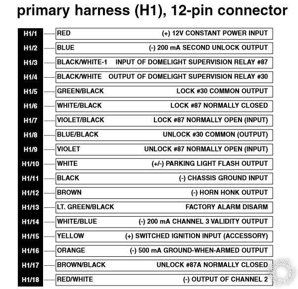
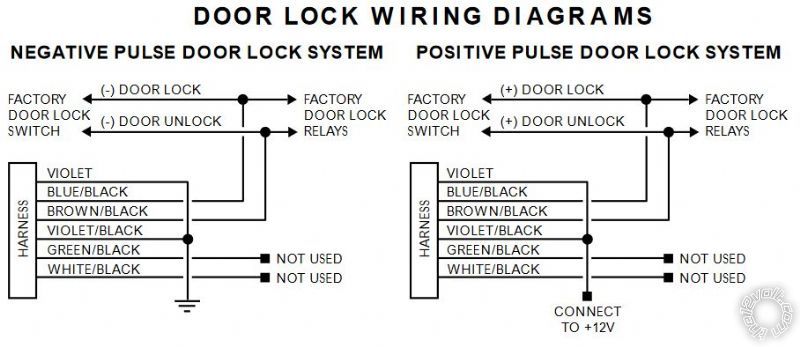
I do hope you can help me with the first and most important step wiring my locks to the harness for a simple lock and unlock of all doors at one time then I'll proceed with the other options I desire. Thank You.
Thank You For Any Help & Your Valuable Time
f250owner 
Member - Posts: 21
Member spacespace
Joined: November 27, 2016
Location: Florida, United States
Posted: November 28, 2016 at 11:22 AM / IP Logged  
To reiterate for anyone who wishes to help me as I forgot to mention that my particular 2004 Ford F-250 for whatever reason came without "GEM" or a "VSM" from the factory. It came from factory with what I believe a Type C power locking system without OEM keyless entry. Hoping this will make an contributions explaining my installation of the Viper Model 211HV keyless remote easier or less complicated.
Thank You For Any Help & Your Valuable Time
davep. 
Gold - Posts: 639
Gold spacespace
Joined: May 27, 2011
Location: California, United States
Posted: November 28, 2016 at 11:45 AM / IP Logged  
The Crew Cab is NOT "5 wire reversing polarity".
In the driver door harness:
Pink/lt green = UNLOCK. (+) trigger.
Pink / YELLOW = LOCK. (+) trigger.
Connect the 211 using the diagram "positive pulse door lock system" in the lower right of your post above.
Test the wires once you find them, before you make the connections. With your VOM, each wire should rest at 0-volts, and go +12volt when lock or unlock is pressed on the door switch.
I confirmed the wire colors from my install notes I've kept in my truck's glove box since the install 8 years ago. The 2004 may be different, but if you find pnk/yel and pnk/lt grn, test to be sure, but those are probably them.
Again, the Crew Cab is NOT "5 wire reversing"
f250owner 
Member - Posts: 21
Member spacespace
Joined: November 27, 2016
Location: Florida, United States
Posted: November 28, 2016 at 2:20 PM / IP Logged  
Ok I'll go test those wires listed below which I already had readily exposed located in the kick panel and test them with my multimeter. If what you say is true this makes connecting things straight forward & much much simpler. Fingers crossed!
Pink/lt green = UNLOCK. (+) trigger.
Pink / YELLOW = LOCK. (+) trigger.
Thank You For Any Help & Your Valuable Time
f250owner 
Member - Posts: 21
Member spacespace
Joined: November 27, 2016
Location: Florida, United States
Posted: November 28, 2016 at 3:50 PM / IP Logged  
I just discovered after I exposed the copper on the targeted colored lock wires I have no choice but to put testing wires on hold due to my instrument speedometer or 'cluster' being currently out of the truck for repair.
There is a module in the cluster enabling power locks/windows so needless to say can't switch locks on or off right now; no cluster plugged in therefore = can't test for + or - 12v on the targeted lock wires.
I expect by Dec 6 I'll have it back. If anyone comes across my thread while I'm waiting I would greatly appreciate any shared knowledge or advice to make my self install of the Viper Model 211HV more straight forward. Until then I'll post back once I'm able to test the lock wires for voltage result once my lock switch is enabled after I plug the cluster back in my truck.
Thank You For Any Help & Your Valuable Time
davep. 
Gold - Posts: 639
Gold spacespace
Joined: May 27, 2011
Location: California, United States
Posted: November 28, 2016 at 6:23 PM / IP Logged  
Pretty sure the locks will still work without the cluster. Locks are powered at all times. The cluster controls the Retained Accessory Power relay. Radio and windows are powered from the RAP. Locks are not.
f250owner 
Member - Posts: 21
Member spacespace
Joined: November 27, 2016
Location: Florida, United States
Posted: November 29, 2016 at 4:01 AM / IP Logged  
I'll double check my connections as the interior of my truck in shambles now due to my installing various different accessories among this keyless entry. If you're correct about the Retained Accessory Power Relay within the cluster having no affect on the power locks then I only hope something unknown is messed up.
I disconnected the lock and window harness plugs/switches as I disassembled my interior's door, dash etc.. earlier before starting my project. I connected them back to utilize the lock switch in this attempt testing those targeted lock wires but now have no working locks seemingly hmmm?
I'll post back later today.
Thank You For Any Help & Your Valuable Time
Page of 2

  Printable version Printable version Post ReplyPost New Topic
You cannot post new topics in this forum
You cannot reply to topics in this forum
You cannot delete your posts in this forum
You cannot edit your posts in this forum
You cannot create polls in this forum
You cannot vote in polls in this forum

  •  
Search the12volt.com
Follow the12volt.com Follow the12volt.com on Facebook
Thursday, March 28, 2024 • Copyright © 1999-2024 the12volt.com, All Rights Reserved Privacy Policy & Use of Cookies
Disclaimer: *All information on this site ( the12volt.com ) is provided "as is" without any warranty of any kind, either expressed or implied, including but not limited to fitness for a particular use. Any user assumes the entire risk as to the accuracy and use of this information. Please verify all wire colors and diagrams before applying any information.

Secured by Sectigo
the12volt.com spacer
Support the12volt.com
Top
the12volt.com spacer