I have a 2008 Ford F250. I will be installing truck bed lights. There will be a total of 8 LED pods which has en extremely low amperage draw (less than 1 amp total). I want to wire it a little more complex than a simple single switch to turn it on/off. I need some help wiring in order for them to operate the way I want.
I want them to turn on in the following three circumstances:
1. By way of a pop-pin switch. The kind that you install so when the tailgate is closed the pin pushes in and turns off the lights. When you open the tailgate the pin pops open and the lights turn on.
Click HERE to see product
2. By a dedicated on/off switch in the cab that I can turn the lights on and off at any time, even when the tailgate is closed.
3. Finally, by tapping into the line that triggers the lights to come on whenever my existing factory bed light comes on (The one above the rear windshield)
My initial thought was to use one relay and connect all three triggers to the 86 terminal inserting a diode on each of the three lines as to not send a signal back to either of the other 2. I am pretty sure this will work, but not sure if the use of diodes is necessary. Also under this method, I am not quite sure how I can have the pop-pin act as a trigger, because the way that switch works is by breaking the circuit at the ground. Not the hot lead. (You install that by connecting the ground from the lights to the spade terminal on the switch. Then the body of the switch is mounted right onto the truck, thereby grounding itself.)
Now being that these lights only draw about 80mAmps (0.8 amps), I was wondering if there is a way I can wire this to my satisfaction without using a relay.
If someone could please steer me in the right direction or suggest the best way to do this I would appreciate it. Please let me know if I need to provide more specifics.


 the12volt
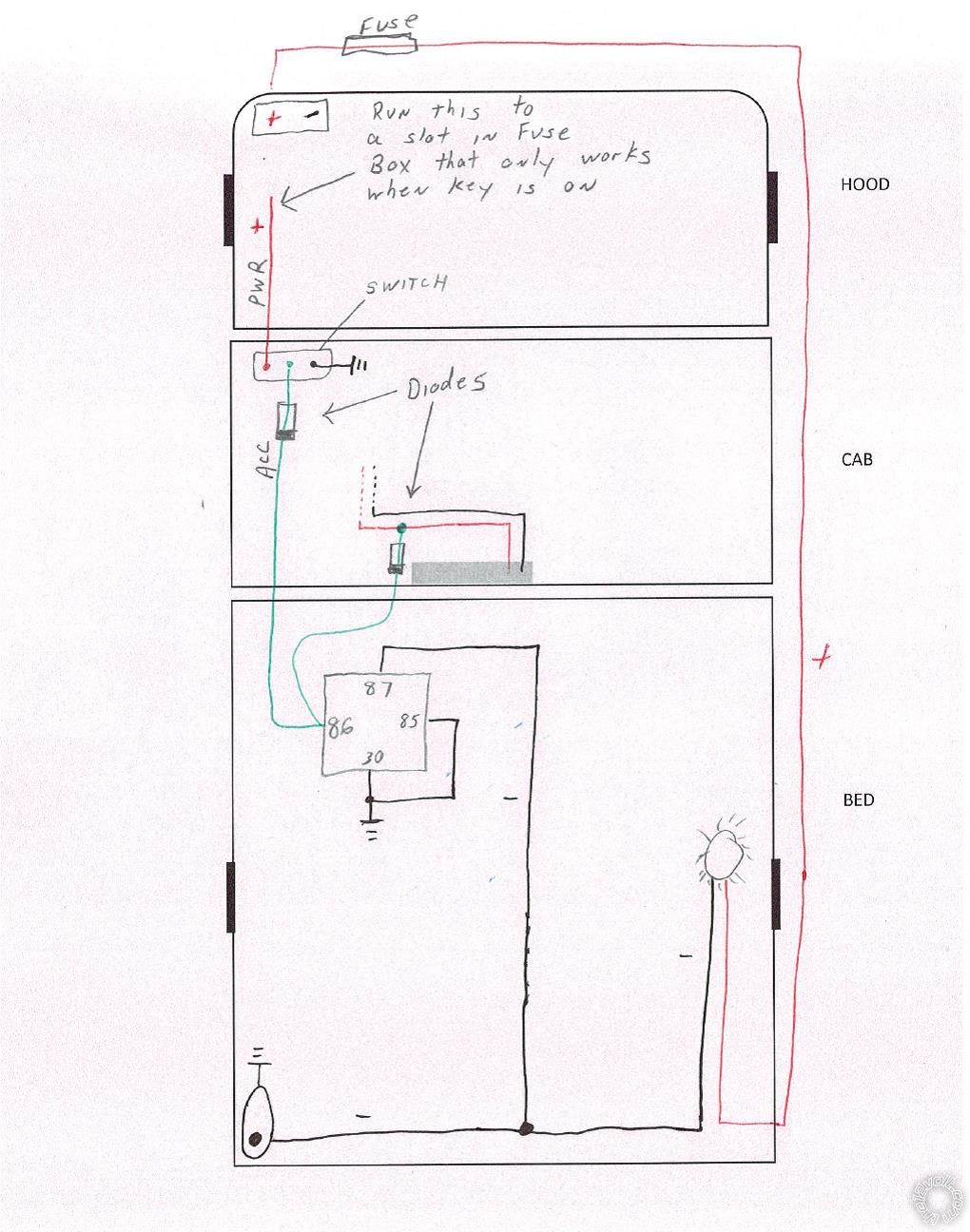
  Now connect all the negative outputs (from on/off switch, pin switch, and relay) to the negative lead of the lights and connect the positive lead of the lights to a constant 12V+ fused source. Diodes aren't necessary, but if you do use them, I would use 2 amp diodes to be on the safe side.
 to add the diagram to your post.
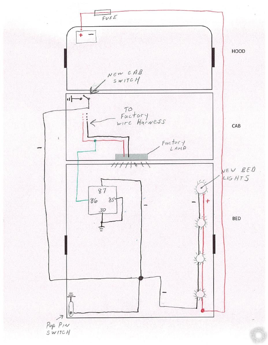 Assuming this diagram is correct I do have 2 questions.
1. The style switch I plan to use in the cab has red and green indicator lights to tell whether it is on or off. (see attachment) I am pretty sure those will not work in this configuration. Am I wrong? Is there a way around that?
2. You mentioned to use an SPDT relay. I typically use a basic 4 prong relay with a 30, 85, 86, and 87 terminal. Can I just use that and attach a jumper wire connecting the 30 and 85 terminal to create what you posted above?
Assuming this diagram is correct I do have 2 questions.
1. The style switch I plan to use in the cab has red and green indicator lights to tell whether it is on or off. (see attachment) I am pretty sure those will not work in this configuration. Am I wrong? Is there a way around that?
2. You mentioned to use an SPDT relay. I typically use a basic 4 prong relay with a 30, 85, 86, and 87 terminal. Can I just use that and attach a jumper wire connecting the 30 and 85 terminal to create what you posted above?

 Printable version


