Update:
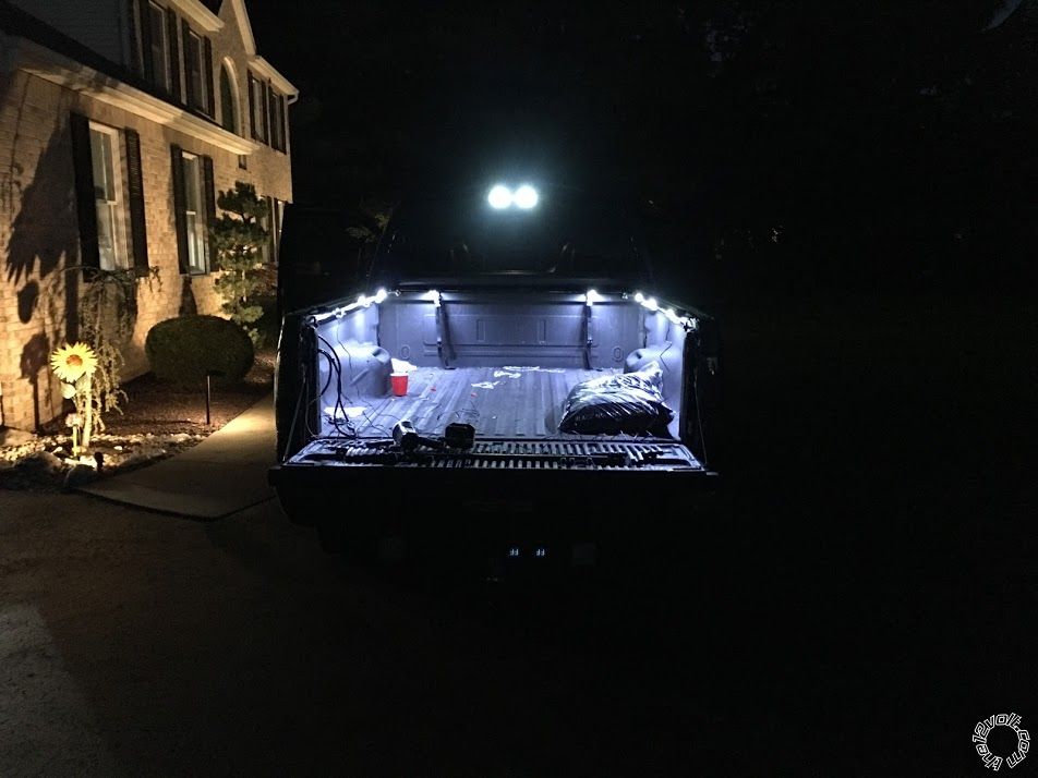
Wow. This turned out to be some project. On paper it looks great. Once you start running the wires, spicing, crimping, shrink wrapping, protecting everything in wire loom, zip tying, etc, it gets very tedious. But for the most part I am done.
Observations regarding diodes:
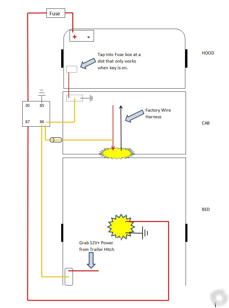
Originally I installed the bed lights with only a diode on the trigger line coming from the factory rear window light as shown below:
 But the problem with that was:
That rear window light goes ON under under numerous scenarios even when the truck is completely off, key out of ignition. For example, if I lock or unlock the truck using my key FOB, that light goes on. If I walk up to the truck and open the door, that light goes on, etc. So this is what I noticed. I would open up the drivers door, lights would turn on. Good so far. But if I turned on my dash switch before the delay would turn off the lights, the power would now run BACKWARDS through that switch, into the fuse box (where I tapped in) and activate the entire fuse box. (Follow on diagram above). This caused all kinds of scary things, such as: I would hear the fuel pump under the hood engage, the engine blower motor would go on, the Glow Plug cycle would start (diesel engine).
Said another way; If I turned on my new dash switch
while the factory light was on, the truck "thought" I stuck the key in the ignition.
Hopefully that makes sense.
The Solution:
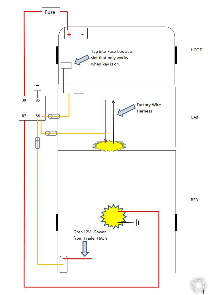
Install a diode on the yellow trigger wire between the relay and the dash switch. For good measure I also installed one on the yellow wire going to the bed switch. I considered installing one on the wire coming from the fuse box to the switch also, to completely control which direction electricity can flow. But I thought this was not necessary as I already blocked flow in that direction from all points of entry. Sure enough I tested it with the news diodes in place and all works well now. So this is what it currently looks like:
 Now regarding getting power to my bed switch:
 (God bless ya if you're still with me - LOL)
We discussed last week that I wanted to tap into my 12V+ at the 7 pin hitch connection in the rear to power my bed switch. But that there was the possibility that the connection wasn't live with the key off. Which ended up being the case. I took Ween's suggestions below and made that live all the time:
Ween wrote:
| In the battery junction box (fuse box under the hood), there should be a relay labeled as trailer tow, battery charge. This is the +12V
that is available at the 7 pin trailer connector, orange wire. However it is controlled by the ignition switch by said relay. If the relay is removed,
and a jumper wire placed between terminals 30 and 87, unswitched power will be available on the wire. Add a fuse inline for the added circuitry (lights)
of course. |
|
|
So now I can walk up to the truck at night; key out, ignition off. Open the tailgate, turn on switch I mounted just to the side of the bed and turn the bed lights on. (Yes I am aware I can drain the battery this way if I forget to turn em off).
Now that orange wire I tapped into at the 7 pin is already protected by a factory fuse in the fuse box. So I don't believe it is necessary to add a fuse where I tapped into it.
Do we agree on this? Remember, that tap is not even powering the bed lights. It's only powering my bed switch which in turn activates the relay. The bed lights themselves are of course on a protected circuit coming straight off the battery (again refer to diagram above).
OK. Long post. Hope everything I discussed here is clear. This has certainly been a learning experience for me.


 the12volt
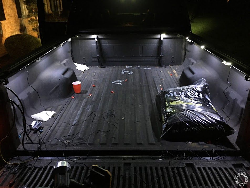
 Printable version


