I cut into the pink/yellow and pink/light green wires. They are behind the drivers side kick panel like you said.
I did not use a fuse on the line to the battery. What amp fuse should I use? The factory harness is utilizing that 30 amp breaker.
I already orded a replacement switch and I'm in the process of putting it back to factory.
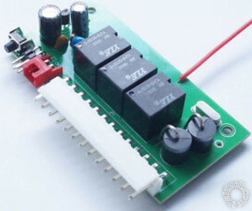
The unit does have onboard relays but I believe thay are only rated for 200ma. The relays have to carry the load to actuate the lock poppers. Everything I read said you had to use relays.
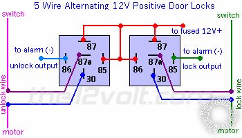
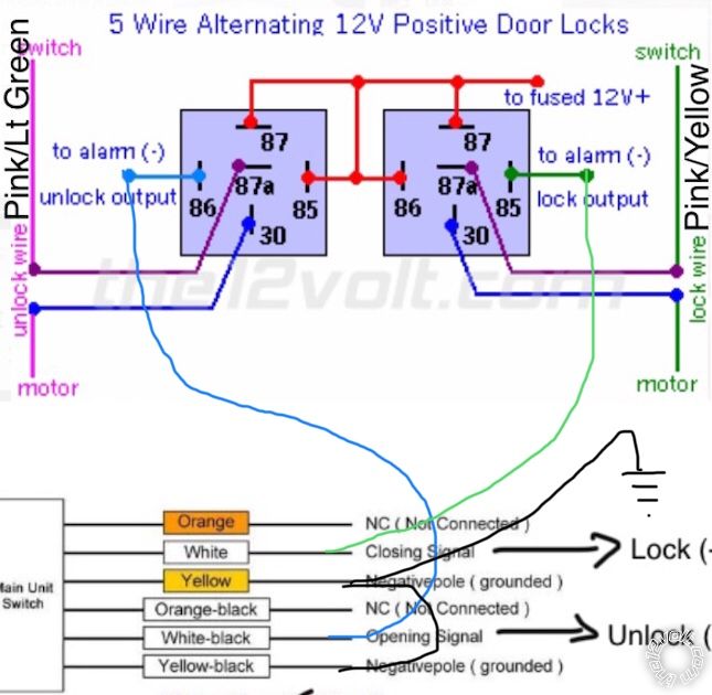
I wired it up as shown in the above diagram with one minor change. In my system I wired both 87 terminals using a 14 gauge wire straight to the battery. For the positively charged post 85 and 86 I ran a separate 18 gauge wire from the battery. Neither wire was fused. This was supposed to be a quick test wire to confirm the system worked then wire it all into the factory system later.
The drivers side rocker switch was obviously damaged in the test. What I don't understand is how the system overloaded unless I have a short somewhere. Before I tried locking/unlocking the system with the keyless system I tested the rocker switches. They worked fine. Then I tried the keyless system and nothing happened. I could hear the relays actuate but the poppers didn't move. Then the switch quit working.
Before the switch was damaged there was an audible click when it was pressed in the lock or unlock position. After it was damaged it just moved back and forth. No click. That's when I opened it up and confirmed it was damaged.
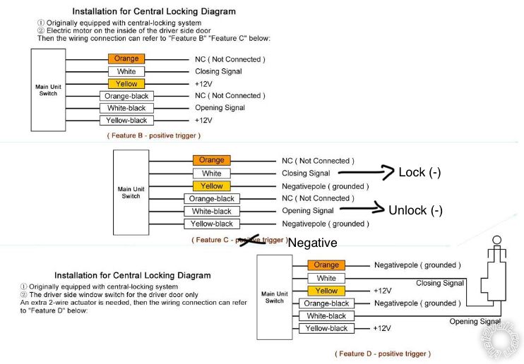
Because it was a temp test the alarm module was sitting on the finder of my car not mounted in the car. I twisted the black negative wire, yellow wire and yellow/black wires together and put them straight to the battery (negative post). The white and white/black wires were used to go to the relays. The power wire on the alarm was also wired straight to the battery but it does have a factory installed fuse on it. Orange and orange/black are not being used. Not sure if any of that matters but thought it should be known.
Thanks for the markup on the diagram. The one that came in the box is actually correct. Still calls it closing and opening though.


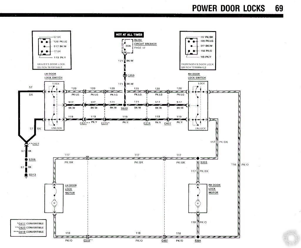 I'm using this wiring diagram from the site as a guide.
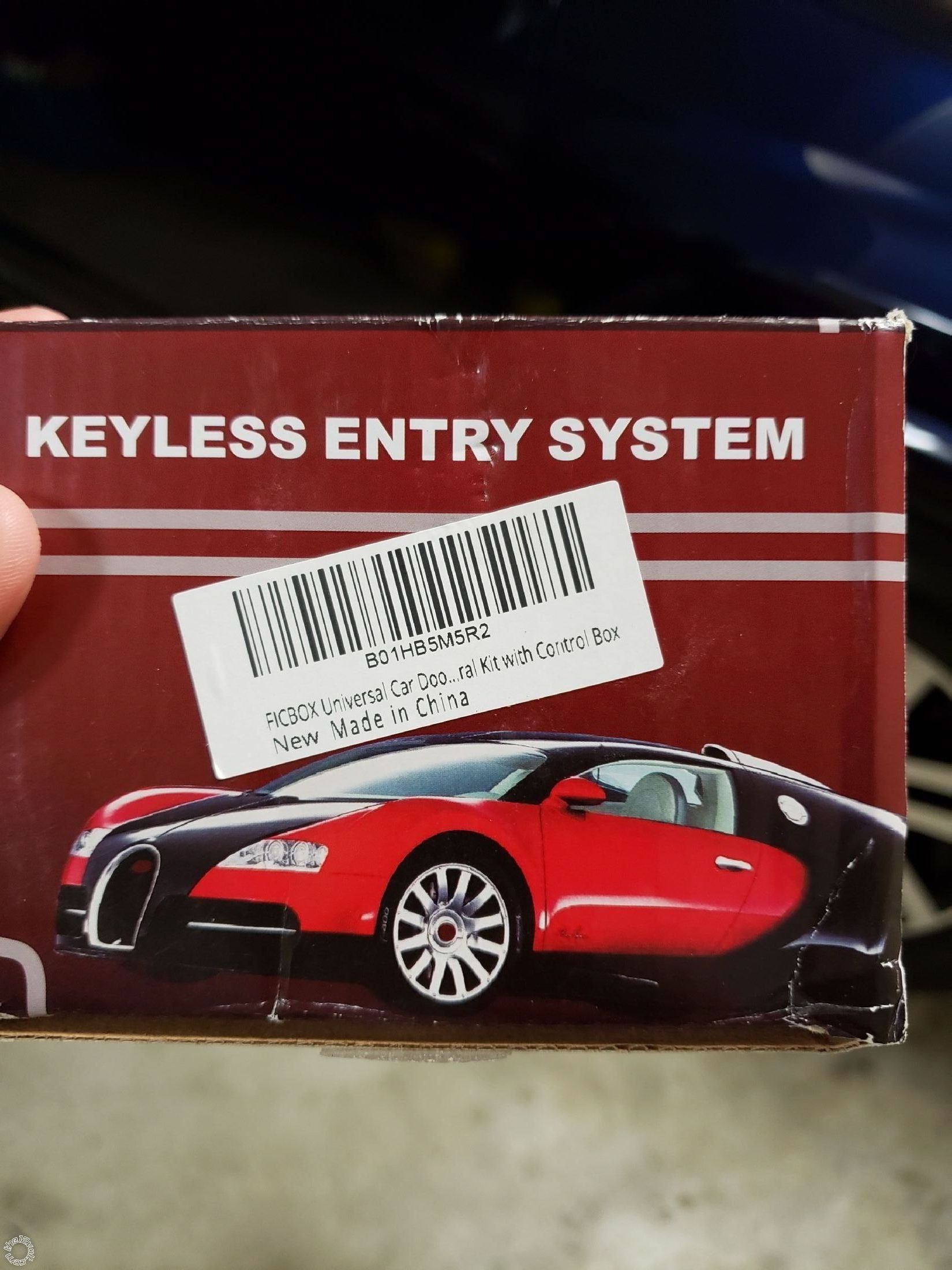
 The kit I bought is a cheap unit made 8n China. This is a pic of the box.
I wired the system up and the locks worked using the rocker switches on the doors. When I tried using the keyless entry they made a little noise but didn't work. After a few tries the door rockets wouldn't even work. I took the driver's side door switch out and it appears to have been over loaded.
Just for testing purposes I wired post 87 straight to the battery with a 14 gauge wire. Post 85 and 86 are wired with a much smaller wire as they don't really carry a load.
Before I hooked up the relays to the car wiring I tested the key fob and the system activated the relays with no issues.
Any ideas why this isn't working?
The kit I bought is a cheap unit made 8n China. This is a pic of the box.
I wired the system up and the locks worked using the rocker switches on the doors. When I tried using the keyless entry they made a little noise but didn't work. After a few tries the door rockets wouldn't even work. I took the driver's side door switch out and it appears to have been over loaded.
Just for testing purposes I wired post 87 straight to the battery with a 14 gauge wire. Post 85 and 86 are wired with a much smaller wire as they don't really carry a load.
Before I hooked up the relays to the car wiring I tested the key fob and the system activated the relays with no issues.
Any ideas why this isn't working?

 Pic of the keyless entry unit.

 I think a 30 amp blade fuse would be best for the relay setup. The 4 power wires can all be together and then run through the fuse.
Im not sure what caused the magic smoke to be released from the switch but make sure both relays are connected to all wires and functioning as a pair when testing. If you only tried testing 1 relay at a time that would definitely cause issues. They need to reverse power and ground simultaneously when triggered and if all wires arent connected then power will be driven into a dead short and fry stuff.
I think a 30 amp blade fuse would be best for the relay setup. The 4 power wires can all be together and then run through the fuse.
Im not sure what caused the magic smoke to be released from the switch but make sure both relays are connected to all wires and functioning as a pair when testing. If you only tried testing 1 relay at a time that would definitely cause issues. They need to reverse power and ground simultaneously when triggered and if all wires arent connected then power will be driven into a dead short and fry stuff.


 Printable version


