the12volt.com spacer
icon

2013 Nissan Pathfinder R51, Remote Start/Alarm, Lock/Unlock, Immobiliser


Post ReplyPost New Topic
< Prev Topic Next Topic >
kreg357 
Platinum - Posts: 7,783
Platinum spaceThis member has made a donation to the12volt.com. Click here for more info.spaceThis member has been recognized as an authority in Electrical Theory. Click here for more info.spaceThis member has been recognized as an authority in Mobile Security and Convenience. Click here for more info.spacespace
Joined: January 30, 2009
Location: Pennsylvania, United States
Posted: February 03, 2020 at 6:31 AM / IP Logged Link to Post Post Reply Quote kreg357
Yes, something is wrong with the Unlock output. It should be similar to the Lock output. I've heard that you can damage them with in appropriate connections. You could try using the Disarm Output. It's not exactly the same functionally as Unlock but should be OK for testing.
On the Immobilizer system, the R/S should duplicate the regular key startup and turn on the chip sensing to see the keys' chip when it outputs the ignition wire outputs. Your Pathfinder should R/S with the 556U unplugged and a key held next top the ignition cylinder or inserted but not turned.
Your vehicle has one Ignition wire, two Starter wires and two Accessory wires. All should be isolated and powered during a R/S. This would require an additional 30/40 Amp SPDT relay controlled by either (-) Starter or (-) Accessory and the Pink/White Flex relay programmed to either Starter or Accessory.
Soldering is fun!
konbra 
Member - Posts: 20
Member spacespace
Joined: February 02, 2020
Location: Australia
Posted: February 03, 2020 at 6:51 AM / IP Logged Link to Post Post Reply Quote konbra
I will send the shop a message regarding the issue and see what can be done as the unit is a bit useless if i can't unlock
Regarding the rest, it seems that I need to rewire some connections.
I will connect the second starter wire with a 30 SPDT relay as you have suggested.
My only problem is I cannot locate the second ignition wire. Everything suggests that there is a second one (which brings up my dash) but I cannot find it anywhere. Every other post on this forum says it is in the ignition harness plug but mine doesn't have it. All other colours match up apart from that one.
So i believe i have 1 acc wire, 2 ign wire and 2 starter wires. This explains why my dash only shows up when my key is turned to IGN - and since I am missing that second wire, my dash isn't lighting up and therefore my immobiliser isn't reading my bypass module.
I simply don't know where this second ignition wire is :(
2013 Nissan Pathfinder 140KW
kreg357 
Platinum - Posts: 7,783
Platinum spaceThis member has made a donation to the12volt.com. Click here for more info.spaceThis member has been recognized as an authority in Electrical Theory. Click here for more info.spaceThis member has been recognized as an authority in Mobile Security and Convenience. Click here for more info.spacespace
Joined: January 30, 2009
Location: Pennsylvania, United States
Posted: February 03, 2020 at 6:58 AM / IP Logged Link to Post Post Reply Quote kreg357
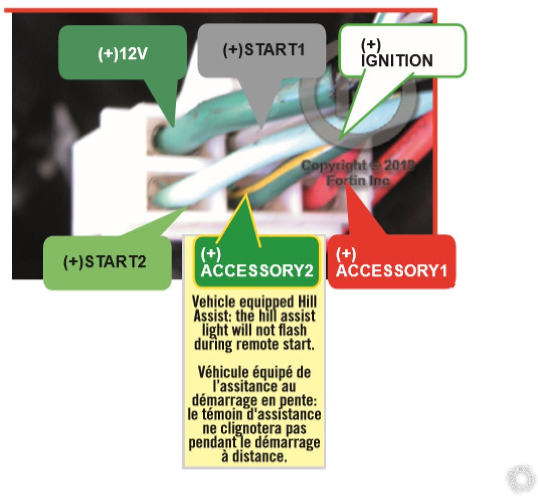
Here is what the main ignition connector looks like for U.S. R51 models :
2013 Nissan Pathfinder R51, Remote Start/Alarm, Lock/Unlock, Immobiliser - Page 2 -- posted image.
There is no IGN2 on U.S. models. Do your wire color and locations match the photo above?
Soldering is fun!
konbra 
Member - Posts: 20
Member spacespace
Joined: February 02, 2020
Location: Australia
Posted: February 03, 2020 at 7:07 AM / IP Logged Link to Post Post Reply Quote konbra
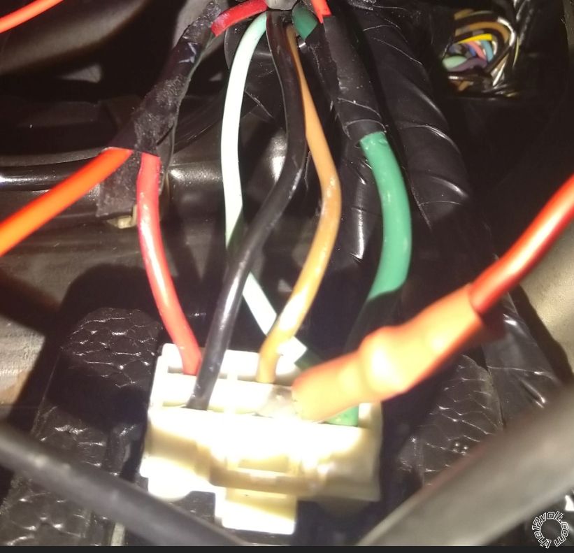
This is what my harness looks like:
I have:
Green: (+) 12V
Brown: ACC
Grey: Starter 1
Light Green: Starter 2
Red: Ignition 1
Black: - I just assumed was ground (-) as it was black so I never tested it, but could it be possible that this is in fact the second wire since the harness that you have shown does not indicate a GROUND (-)
2013 Nissan Pathfinder R51, Remote Start/Alarm, Lock/Unlock, Immobiliser - Page 2 -- posted image.
2013 Nissan Pathfinder 140KW
kreg357 
Platinum - Posts: 7,783
Platinum spaceThis member has made a donation to the12volt.com. Click here for more info.spaceThis member has been recognized as an authority in Electrical Theory. Click here for more info.spaceThis member has been recognized as an authority in Mobile Security and Convenience. Click here for more info.spacespace
Joined: January 30, 2009
Location: Pennsylvania, United States
Posted: February 03, 2020 at 7:12 AM / IP Logged Link to Post Post Reply Quote kreg357
Possibly, I've never seen a Chassis Ground in a high current ignition connector but I've seen Black wire used for various type wires.
Seems your wiring is very different from U.S. models.
Soldering is fun!
konbra 
Member - Posts: 20
Member spacespace
Joined: February 02, 2020
Location: Australia
Posted: February 03, 2020 at 7:16 AM / IP Logged Link to Post Post Reply Quote konbra
Ok i will give this one a test tomorrow and see if it is IGN2 or ACC 2 as it is 23:15 now in Australia, QLD.
I was also going to wire the second starter like this with a SPDT:
30: Starter 2
85: 200mA Starter Output (-)
86+87: +12v (Constant/fused)
87a: unused
2013 Nissan Pathfinder 140KW
kreg357 
Platinum - Posts: 7,783
Platinum spaceThis member has made a donation to the12volt.com. Click here for more info.spaceThis member has been recognized as an authority in Electrical Theory. Click here for more info.spaceThis member has been recognized as an authority in Mobile Security and Convenience. Click here for more info.spacespace
Joined: January 30, 2009
Location: Pennsylvania, United States
Posted: February 03, 2020 at 7:30 AM / IP Logged Link to Post Post Reply Quote kreg357
Yes, relay wiring is good.
It's almost tomorrow in OZ....   2013 Nissan Pathfinder R51, Remote Start/Alarm, Lock/Unlock, Immobiliser - Page 2 -- posted image.
Soldering is fun!
konbra 
Member - Posts: 20
Member spacespace
Joined: February 02, 2020
Location: Australia
Posted: February 03, 2020 at 7:32 AM / IP Logged Link to Post Post Reply Quote konbra
ALso the pink/white flex relay. I thought that it automatically gets changed depending how it is wired up. Or do I need to program it myself, depending on if i even use it based on that black wire.
2013 Nissan Pathfinder 140KW
kreg357 
Platinum - Posts: 7,783
Platinum spaceThis member has made a donation to the12volt.com. Click here for more info.spaceThis member has been recognized as an authority in Electrical Theory. Click here for more info.spaceThis member has been recognized as an authority in Mobile Security and Convenience. Click here for more info.spacespace
Joined: January 30, 2009
Location: Pennsylvania, United States
Posted: February 03, 2020 at 7:49 AM / IP Logged Link to Post Post Reply Quote kreg357
The Pink/White Flex relay comes set as IGN2 as default. You can change it via option programming to ACC2 according to the 5305 manual. Guess it can't be set to Starter2. See Menu 3, Item 6.
Soldering is fun!
konbra 
Member - Posts: 20
Member spacespace
Joined: February 02, 2020
Location: Australia
Posted: February 03, 2020 at 4:56 PM / IP Logged Link to Post Post Reply Quote konbra
Ok well I will be home in a few hours (at work), I will first test that black wire and confirm whether it is an ACC2 or IGN2.
Ill then do the following:
1) connect the red/white wire to a constant 12v fused source
2) connect the pink/white to either the ACC2 or IGN2 (whatever that black wire is)
3) connect a SPDT relay
4) Remote start and keep a fire extinguisher nearby hahaha
2013 Nissan Pathfinder 140KW
Page of 4

  Printable version Printable version Post ReplyPost New Topic
You cannot post new topics in this forum
You cannot reply to topics in this forum
You cannot delete your posts in this forum
You cannot edit your posts in this forum
You cannot create polls in this forum
You cannot vote in polls in this forum

  •  
Search the12volt.com
Follow the12volt.com Follow the12volt.com on Facebook
Friday, May 3, 2024 • Copyright © 1999-2024 the12volt.com, All Rights Reserved Privacy Policy & Use of Cookies
Disclaimer: *All information on this site ( the12volt.com ) is provided "as is" without any warranty of any kind, either expressed or implied, including but not limited to fitness for a particular use. Any user assumes the entire risk as to the accuracy and use of this information. Please verify all wire colors and diagrams before applying any information.

Secured by Sectigo
the12volt.com spacer
Support the12volt.com
Top
the12volt.com spacer