the12volt.com spacer
icon

2015 Subaru Impreza, Avital 4105


Post ReplyPost New Topic
< Prev Topic Next Topic >
kreg357 
Platinum - Posts: 7,783
Platinum spaceThis member has made a donation to the12volt.com. Click here for more info.spaceThis member has been recognized as an authority in Electrical Theory. Click here for more info.spaceThis member has been recognized as an authority in Mobile Security and Convenience. Click here for more info.spacespace
Joined: January 30, 2009
Location: Pennsylvania, United States
Posted: May 25, 2020 at 9:32 AM / IP Logged Link to Post Post Reply Quote kreg357
Here are the ignition wires :
Ignition #1   GREEN   IGNITION SWITCH WHITE 8 PIN CONN, PIN 1
Ignition #2   BLUE (+)   IGNITION SWITCH WHITE 8 PIN CONN, PIN 6
Accessory #1   YELLOW (+)   IGNITION SWITCH WHITE 8 PIN CONN, PIN 2
Starter #1   BLACK/WHITE   IGNITION SWITCH WHITE 8 PIN CONN, PIN 3
Starter #2   WHITE (+)   IGNITION SWITCH WHITE 8 PIN CONN, PIN 7
You need to power the Starter2 wire using a 30/40 Amp SPDT relay. Wiring shown below :
Relay Pins 86 and 87 to White +12V Constant thru 30 Amp fuse
Relay Pin 30 to White (+) Starter ( might be White/Blue )
Relay Pin 85 to Avital thin PURPLE (-) 200mA STARTER OUTPUT
Be aware that there are possibly two White wires in the ignition switch harness, one is +12V constant and the other is Starter2.
Test to be sure. Here is a pin-out of that plug :
2015 Subaru Impreza, Avital 4105 - Page 3 -- posted image.
After you get the ignition wiring completed, you can test the bypass module again via a R/S. It is possible that the loop around the ignition switch needs to be re-positioned for best performance.
Soldering is fun!
avrohom24 
Member - Posts: 31
Member spacespace
Joined: May 18, 2020
Location: New Jersey, United States
Posted: May 25, 2020 at 9:45 AM / IP Logged Link to Post Post Reply Quote avrohom24
thank You so much Kreg357 and geepherder!
Im going to get working on that relay (always avoided them; they look scary). Do I go to a Lowes store or do i need to go to an Automotive store for the relay?
ays
kreg357 
Platinum - Posts: 7,783
Platinum spaceThis member has made a donation to the12volt.com. Click here for more info.spaceThis member has been recognized as an authority in Electrical Theory. Click here for more info.spaceThis member has been recognized as an authority in Mobile Security and Convenience. Click here for more info.spacespace
Joined: January 30, 2009
Location: Pennsylvania, United States
Posted: May 25, 2020 at 10:20 AM / IP Logged Link to Post Post Reply Quote kreg357
Not sure where they are available. Probably an Auto parts store would be best. I get mine from an online distributor in lots of 100.
Try to get one with the 5 pin harness. It will make it easier to install. You could get a SPST relay with just 4 pins ( no Pin 87a ).
They will work for your application.
Soldering is fun!
avrohom24 
Member - Posts: 31
Member spacespace
Joined: May 18, 2020
Location: New Jersey, United States
Posted: May 25, 2020 at 1:40 PM / IP Logged Link to Post Post Reply Quote avrohom24
Unfortunately no body local had the correct one, i had to order from Amazon and it wont be here till next week (thats with Prime!!!)
Please don't run off on me before then, I need you guys!
ays
kreg357 
Platinum - Posts: 7,783
Platinum spaceThis member has made a donation to the12volt.com. Click here for more info.spaceThis member has been recognized as an authority in Electrical Theory. Click here for more info.spaceThis member has been recognized as an authority in Mobile Security and Convenience. Click here for more info.spacespace
Joined: January 30, 2009
Location: Pennsylvania, United States
Posted: May 25, 2020 at 2:06 PM / IP Logged Link to Post Post Reply Quote kreg357
We'll be here.
Did you get the Parking Lights sorted out? I usually use the (-)Parking Light wire. You can use your DMM to locate this wire. Set to 20 V DC. Red test lead to +12V constant and Black test lead to suspect wire below :
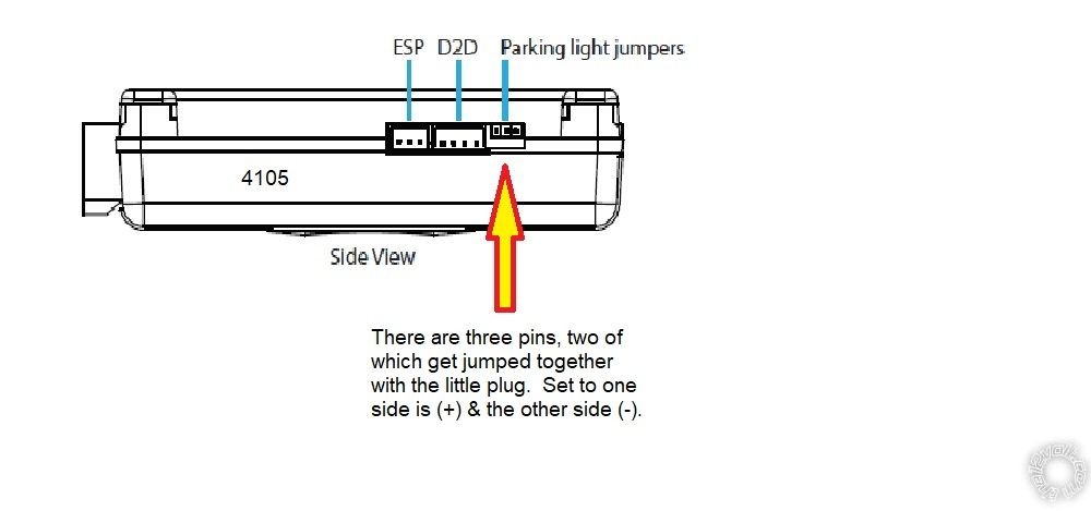
PARKING LIGHTS ( - )    BLACK/BLUE (-)    @ HEADLIGHT Switch, WHITE 20-Pin Plug, Pin 18. The Headlight Switch plug is in the steering column. With a Subaru, make sure the Parking Lights come on as you might need to start the engine. When you put the Parking Light switch to ON, you will see +12V on the DMM. Next make sure the Avital 4105 Parking Light jumper geepherder mentioned is set to the (-) position. From the factory, they are usually in the (+) position. Diagram below :
2015 Subaru Impreza, Avital 4105 - Page 3 -- posted image.
Soldering is fun!
avrohom24 
Member - Posts: 31
Member spacespace
Joined: May 18, 2020
Location: New Jersey, United States
Posted: May 25, 2020 at 2:11 PM / IP Logged Link to Post Post Reply Quote avrohom24
My luck that my Avital came missing those 3 harnesses on the side view. I didn't realize I needed them, but Im going to have to get it from the seller
ays
kreg357 
Platinum - Posts: 7,783
Platinum spaceThis member has made a donation to the12volt.com. Click here for more info.spaceThis member has been recognized as an authority in Electrical Theory. Click here for more info.spaceThis member has been recognized as an authority in Mobile Security and Convenience. Click here for more info.spacespace
Joined: January 30, 2009
Location: Pennsylvania, United States
Posted: May 25, 2020 at 3:11 PM / IP Logged Link to Post Post Reply Quote kreg357
The one for the Parking lights isn't a harness. It's just a little black plastic jumper that covers/shorts two of the three pins together. They can come loose from shipping but usually don't. Look closely to see if it's there and on the (+) side. If it's missing check the box or plastic bag. Otherwise you might find one on an old PC card or motherboard. The pin spacing is always the same.
Once the jumper is set, the 4105's White Parking Light output wire on the Main 9 Pin Harness will be connected to the vehicle (-) Parking Light wire.
Soldering is fun!
avrohom24 
Member - Posts: 31
Member spacespace
Joined: May 18, 2020
Location: New Jersey, United States
Posted: May 25, 2020 at 3:16 PM / IP Logged Link to Post Post Reply Quote avrohom24
Still looking for the tach wire. The wiring diagrams say its pin 51, 52, 53, and 54 behind the engine. i tried tapping to 54 and I don't think it was right. Looking on a Subaru forum it seems some say it is not correct. Some say there's a green wire behind the instrument cluster while others claim there isn't. Some say the only place to pick it up is by the ECU. I was wondering if any of you knows where it is. Its a 4 door sedan 2015 Subaru Impreza Automatic
Also, if anyone knows where the trunk latch wire is in the drivers side it would be helpful as the wiring diagram sends me inconveniently to the passenger kick
Thank You
ays
avrohom24 
Member - Posts: 31
Member spacespace
Joined: May 18, 2020
Location: New Jersey, United States
Posted: May 25, 2020 at 3:17 PM / IP Logged Link to Post Post Reply Quote avrohom24
Thank You Kreg357, I found it; Ill let you know how it goes
ays
kreg357 
Platinum - Posts: 7,783
Platinum spaceThis member has made a donation to the12volt.com. Click here for more info.spaceThis member has been recognized as an authority in Electrical Theory. Click here for more info.spaceThis member has been recognized as an authority in Mobile Security and Convenience. Click here for more info.spacespace
Joined: January 30, 2009
Location: Pennsylvania, United States
Posted: May 25, 2020 at 3:39 PM / IP Logged Link to Post Post Reply Quote kreg357
The Trunk Release can be found at the BCM but that is behind the Fuse Box. Here is the info :
Trunk Release    GREEN/RED (-)    BCM BLACK 35 PIN CONN, PIN 10
It might be easier to extend the 4105 Trunk Release wire with a piece of unused 4105 harness wire, like the Yellow (+) Ignition Output ( to alarm ) wire, via solder and heat shrink tube over to the PKP.
For the Tach, you can go to any F.I. non-common wire but they can be difficult to get to. I always use a bypass module that takes care of the transponder ( no lost/hidden key ), the alarm system and supplies a Tach signal.
Soldering is fun!
Page of 5

  Printable version Printable version Post ReplyPost New Topic
You cannot post new topics in this forum
You cannot reply to topics in this forum
You cannot delete your posts in this forum
You cannot edit your posts in this forum
You cannot create polls in this forum
You cannot vote in polls in this forum

  •  
Search the12volt.com
Follow the12volt.com Follow the12volt.com on Facebook
Thursday, April 18, 2024 • Copyright © 1999-2024 the12volt.com, All Rights Reserved Privacy Policy & Use of Cookies
Disclaimer: *All information on this site ( the12volt.com ) is provided "as is" without any warranty of any kind, either expressed or implied, including but not limited to fitness for a particular use. Any user assumes the entire risk as to the accuracy and use of this information. Please verify all wire colors and diagrams before applying any information.

Secured by Sectigo
the12volt.com spacer
Support the12volt.com
Top
the12volt.com spacer