the12volt.com spacer
icon

2001 Jeep Cherokee, Viper 5806V


Post ReplyPost New Topic
< Prev Topic Next Topic >
kreg357 
Platinum - Posts: 7,783
Platinum spaceThis member has made a donation to the12volt.com. Click here for more info.spaceThis member has been recognized as an authority in Electrical Theory. Click here for more info.spaceThis member has been recognized as an authority in Mobile Security and Convenience. Click here for more info.spacespace
Joined: January 30, 2009
Location: Pennsylvania, United States
Posted: February 02, 2021 at 2:44 AM / IP Logged  
firefighter1466 wrote:
Also for the White/Tan above the brake, there are 2 going into the same slot in the harness connector. Do I need to tie into both of them, or just one will suffice? I would think one since they're going in together.
If they are combined at the connector, you can use either one. This is only an input wire for the Viper and doesn't draw any current.
Soldering is fun!
kreg357 
Platinum - Posts: 7,783
Platinum spaceThis member has made a donation to the12volt.com. Click here for more info.spaceThis member has been recognized as an authority in Electrical Theory. Click here for more info.spaceThis member has been recognized as an authority in Mobile Security and Convenience. Click here for more info.spacespace
Joined: January 30, 2009
Location: Pennsylvania, United States
Posted: February 02, 2021 at 2:54 AM / IP Logged  
On the Yellow (-) Door Pin wire, the thick wire in the DKP doesn't look right. One wire listing indicates it will be in a Gray 2 Pin connector. It is easy enough to test it using the DMM as described previously. The correct wire will show +12V when the door is open.
Soldering is fun!
firefighter1466 
Member - Posts: 33
Member spacespace
Joined: January 30, 2021
Location: Virginia, United States
Posted: February 02, 2021 at 8:05 AM / IP Logged  
Should most wires be similarly sized or will there be a few that may be smaller/larger than each other?
Jon
kreg357 
Platinum - Posts: 7,783
Platinum spaceThis member has made a donation to the12volt.com. Click here for more info.spaceThis member has been recognized as an authority in Electrical Theory. Click here for more info.spaceThis member has been recognized as an authority in Mobile Security and Convenience. Click here for more info.spacespace
Joined: January 30, 2009
Location: Pennsylvania, United States
Posted: February 02, 2021 at 8:30 AM / IP Logged  
On your older Jeep, I would think most will be nearly the same size. The Parking Light wire might be slightly different gauge. Obviously, any big differences should be re-checked/verified with the DMM. Some newer cars do have major differences in the ignition wires.
Soldering is fun!
firefighter1466 
Member - Posts: 33
Member spacespace
Joined: January 30, 2021
Location: Virginia, United States
Posted: February 02, 2021 at 8:43 AM / IP Logged  
The parking light was slightly larger. It was a much smaller wire inside of the headlight switch and the white wire from my kit was right much larger. The only other one that I can think of right off hand is the brown wire that goes through the firewall to the siren. They designed these to go together, but the red wire is super small compared to that brown wire. I think most everything else has matched up one for one. Got a few more to go and I'll be able to test everything before mounting the box.
I would imagine once I get everything wired, I can reconnect the battery, close the hood (hood pin switch), connect the harnesses to the box and then connect the control center piece to it and do the program? I would imagine I should be able to fire it up like normal before even doing that to make sure that everything is connected correctly for the ignition portion. I feel most confident in the ignition wires and others because they stood out more than all of the other column wires as they were thicker gauge wire and matched up with the harnesses.
Jon
kreg357 
Platinum - Posts: 7,783
Platinum spaceThis member has made a donation to the12volt.com. Click here for more info.spaceThis member has been recognized as an authority in Electrical Theory. Click here for more info.spaceThis member has been recognized as an authority in Mobile Security and Convenience. Click here for more info.spacespace
Joined: January 30, 2009
Location: Pennsylvania, United States
Posted: February 02, 2021 at 10:02 AM / IP Logged  
Sequence sounds good. I usually do the install hot and just leave the fuses out of the R/S unit. Once everything is connected, you can test with a Lock and Unlock. The door locks should work and the Parking Lights should flash. You can also test the Viper alarm function and siren. The remote start function is in-op due to the Viper being in Manual Transmission Mode. Next would be Viper programming. Set to Auto Trans and Tach Mode. Then start the engine with the key and allow to warm up. Turn it off and the do the Tach Learn. If successful, turn off the vehicle and try a remote start. Test the Brake shutdown and the hood pin shutdown.
Soldering is fun!
firefighter1466 
Member - Posts: 33
Member spacespace
Joined: January 30, 2021
Location: Virginia, United States
Posted: February 02, 2021 at 4:25 PM / IP Logged  
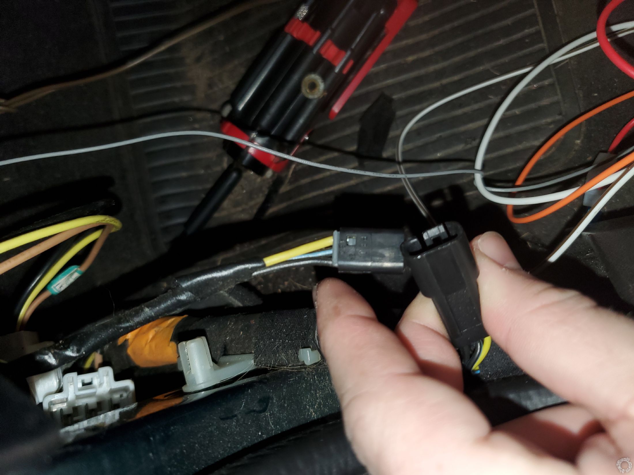
Re the yellow door wire. I didn't find a gray 3 pin connector, but I found a 2 pin connector behind the kick plate that runs along the floor next to the side trim at the bottom. When the park lights are on and the door is open the door makes a dinging sound. When I disconnect this plug the sound goes off. When I close the door this sound goes off. Would this be the correct yellow wire? I have attached an image. I don't have an exposed 12v constant to tap into in order to test unless you have a better alternative for testing.
2001 Jeep Cherokee, Viper 5806V - Page 3 -- posted image.
Jon
firefighter1466 
Member - Posts: 33
Member spacespace
Joined: January 30, 2021
Location: Virginia, United States
Posted: February 02, 2021 at 5:02 PM / IP Logged  
Also - RE: Next would be Viper programming. Set to Auto Trans and Tach Mode. Then start the engine with the key and allow to warm up. Turn it off and the do the Tach Learn. If successful, turn off the vehicle and try a remote start. Test the Brake shutdown and the hood pin shutdown.
How would I do this part? As far as set to Auto Trans and Tach Mode?
Jon
kreg357 
Platinum - Posts: 7,783
Platinum spaceThis member has made a donation to the12volt.com. Click here for more info.spaceThis member has been recognized as an authority in Electrical Theory. Click here for more info.spaceThis member has been recognized as an authority in Mobile Security and Convenience. Click here for more info.spacespace
Joined: January 30, 2009
Location: Pennsylvania, United States
Posted: February 02, 2021 at 5:17 PM / IP Logged  
Re Yellow Door Pin wire - yes that looks like it. My info posted above said Gray 2 Pin plug. Again, the correct way to do this is with a test using a DMM.
Re Viper Programming :   Page 2 of the 2 page install guide included with the Viper system has the program change procedure using the supplied remotes. Menu 3, Item 1 and Item 2 are the two options that need to be changed. You will need the Door Pin functional to enter in to Programming Mode.
Soldering is fun!
firefighter1466 
Member - Posts: 33
Member spacespace
Joined: January 30, 2021
Location: Virginia, United States
Posted: February 02, 2021 at 5:50 PM / IP Logged  
I understand that would be the best way to do it but what do you recommend as an alternate or easier way to check when i dont have an exposed 12V constant?
Jon
Page of 6

  Printable version Printable version Post ReplyPost New Topic
You cannot post new topics in this forum
You cannot reply to topics in this forum
You cannot delete your posts in this forum
You cannot edit your posts in this forum
You cannot create polls in this forum
You cannot vote in polls in this forum

  •  
Search the12volt.com
Follow the12volt.com Follow the12volt.com on Facebook
Friday, April 26, 2024 • Copyright © 1999-2024 the12volt.com, All Rights Reserved Privacy Policy & Use of Cookies
Disclaimer: *All information on this site ( the12volt.com ) is provided "as is" without any warranty of any kind, either expressed or implied, including but not limited to fitness for a particular use. Any user assumes the entire risk as to the accuracy and use of this information. Please verify all wire colors and diagrams before applying any information.

Secured by Sectigo
the12volt.com spacer
Support the12volt.com
Top
the12volt.com spacer