the12volt.com spacer
icon

Wig-Wag Diagram


Post ReplyPost New Topic
< Prev Topic Next Topic >
chasesaccessori 
Copper - Posts: 198
Copper spacespace
Joined: August 22, 2002
Location: United States
Posted: April 08, 2004 at 2:42 PM / IP Logged  
maybe you can add this diagram to your data base.
Wig-Wag Diagram -- posted image.
(owner/installer)
Chase's Accessories
Ridgecrest, CA
in business since 92
the12volt 
Administrator - Posts: 3,955
Administrator spaceThis member has made a donation to the12volt.com. Click here for more info.spaceThis member has been recognized as an authority in Electrical Theory. Click here for more info.spaceThis member has been recognized as an authority in Mobile Audio and Video. Click here for more info.spaceThis member has been recognized as an authority in Mobile Security and Convenience. Click here for more info.spacespace
Joined: March 07, 2002
Location: Louisiana, United States
Posted: April 08, 2004 at 3:00 PM / IP Logged  
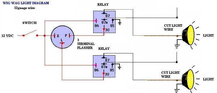
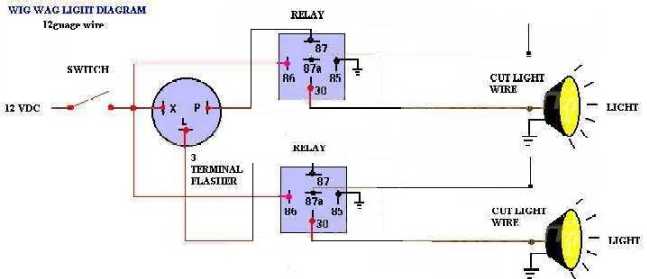
Hi chasesaccessori, will be happy to add a diagram like you have, but I see a problem with your diagram. The lead going to each light should be connected to terminal 30 of each relay respectively, the outputs from the flasher should be connected to terminal 87 of each relay respectively and the switch side of each light should be connected to terminal 87a of each relay respectively. The way it is shown in your diagram now, 12V+ will be sent to the switch side of each light instead of the light itself when 12V+ is supplied by the switch in your diagram.
Wig-Wag Diagram -- posted image. the12volt • Support the12volt.com
the12volt 
Administrator - Posts: 3,955
Administrator spaceThis member has made a donation to the12volt.com. Click here for more info.spaceThis member has been recognized as an authority in Electrical Theory. Click here for more info.spaceThis member has been recognized as an authority in Mobile Audio and Video. Click here for more info.spaceThis member has been recognized as an authority in Mobile Security and Convenience. Click here for more info.spacespace
Joined: March 07, 2002
Location: Louisiana, United States
Posted: April 08, 2004 at 3:01 PM / IP Logged  
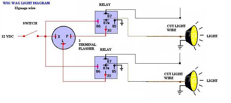
Ahh, I see you changed your diagram.
Wig-Wag Diagram -- posted image. the12volt • Support the12volt.com
the12volt 
Administrator - Posts: 3,955
Administrator spaceThis member has made a donation to the12volt.com. Click here for more info.spaceThis member has been recognized as an authority in Electrical Theory. Click here for more info.spaceThis member has been recognized as an authority in Mobile Audio and Video. Click here for more info.spaceThis member has been recognized as an authority in Mobile Security and Convenience. Click here for more info.spacespace
Joined: March 07, 2002
Location: Louisiana, United States
Posted: April 08, 2004 at 3:03 PM / IP Logged  

Your original diagram here was what I was initially replying to.

Wig-Wag Diagram -- posted image.
Wig-Wag Diagram -- posted image. the12volt • Support the12volt.com
the12volt 
Administrator - Posts: 3,955
Administrator spaceThis member has made a donation to the12volt.com. Click here for more info.spaceThis member has been recognized as an authority in Electrical Theory. Click here for more info.spaceThis member has been recognized as an authority in Mobile Audio and Video. Click here for more info.spaceThis member has been recognized as an authority in Mobile Security and Convenience. Click here for more info.spacespace
Joined: March 07, 2002
Location: Louisiana, United States
Posted: April 08, 2004 at 3:06 PM / IP Logged  
BTW, your second diagram still has a problem. When you attempt to turn on the lights with the switch in the vehicle, 12V+ will be sent to the flasher outputs instead of the lights.
Wig-Wag Diagram -- posted image. the12volt • Support the12volt.com
chasesaccessori 
Copper - Posts: 198
Copper spacespace
Joined: August 22, 2002
Location: United States
Posted: April 08, 2004 at 3:42 PM / IP Logged  
Your right. Man, I have ht hardest time remembering how relays work unless I have one right here in front of me.
(owner/installer)
Chase's Accessories
Ridgecrest, CA
in business since 92
chasesaccessori 
Copper - Posts: 198
Copper spacespace
Joined: August 22, 2002
Location: United States
Posted: April 08, 2004 at 3:50 PM / IP Logged  
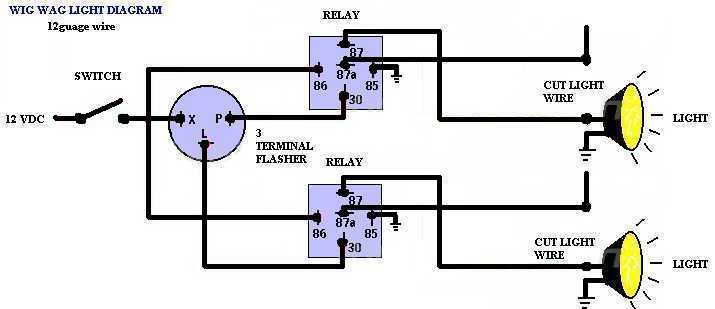
here it is correct.
Wig-Wag Diagram -- posted image.
(owner/installer)
Chase's Accessories
Ridgecrest, CA
in business since 92
the12volt 
Administrator - Posts: 3,955
Administrator spaceThis member has made a donation to the12volt.com. Click here for more info.spaceThis member has been recognized as an authority in Electrical Theory. Click here for more info.spaceThis member has been recognized as an authority in Mobile Audio and Video. Click here for more info.spaceThis member has been recognized as an authority in Mobile Security and Convenience. Click here for more info.spacespace
Joined: March 07, 2002
Location: Louisiana, United States
Posted: April 08, 2004 at 5:27 PM / IP Logged  

Koo ;)

Wig-Wag Diagram -- posted image. the12volt • Support the12volt.com
BumpNGlow 
Member - Posts: 43
Member spacespace
Joined: March 24, 2003
Location: United States
Posted: April 08, 2004 at 7:43 PM / IP Logged  
details on where to get a Terminal Flasher some what cheaply?  Thanks for the diagram.  Is there any easy way to add in a potentometer to make the speed adjustable?  Thanks again
chasesaccessori 
Copper - Posts: 198
Copper spacespace
Joined: August 22, 2002
Location: United States
Posted: April 12, 2004 at 10:13 AM / IP Logged  
Wig-Wag Diagram -- posted image.
hope this is better
(owner/installer)
Chase's Accessories
Ridgecrest, CA
in business since 92
Page of 4

  Printable version Printable version Post ReplyPost New Topic
You cannot post new topics in this forum
You cannot reply to topics in this forum
You cannot delete your posts in this forum
You cannot edit your posts in this forum
You cannot create polls in this forum
You cannot vote in polls in this forum

  •  
Search the12volt.com
Follow the12volt.com Follow the12volt.com on Facebook
Friday, April 26, 2024 • Copyright © 1999-2024 the12volt.com, All Rights Reserved Privacy Policy & Use of Cookies
Disclaimer: *All information on this site ( the12volt.com ) is provided "as is" without any warranty of any kind, either expressed or implied, including but not limited to fitness for a particular use. Any user assumes the entire risk as to the accuracy and use of this information. Please verify all wire colors and diagrams before applying any information.

Secured by Sectigo
the12volt.com spacer
Support the12volt.com
Top
the12volt.com spacer