the12volt.com spacer
icon

Door popping circuit


Post ReplyPost New Topic
< Prev Topic Next Topic >
paulieA 
Member - Posts: 32
Member spacespace
Joined: July 21, 2005
Location: United Kingdom
Posted: July 22, 2005 at 6:46 AM / IP Logged  

The magnet thing is interesting, i was thinking something similar with a barcode or thumb print reader behind the glass. Unfortunately, for saftey reasons over here in the UK you need to have a "physical" means to enter the car from the outside, such as a button or handle. Just having no obvious means to get in means your car will not be deemed road worthy.

Powermyster, this is the sort of thing i was interested in. Agree'd, when you "unlock" the doors with the key fob, it is just a pulse that goes through the system to the solenoid, and as such does not remain active. Is there a means that once you have pressed this button on the fob, it clicks over a relay and then the "popping" circuit will have power for say 30 seconds, thus giving you time to actually press the popping switch to open the door?

The light in the car only comes on with a physical switch, or when the door is ajar as it operates on a push switch in the door jam. Having it come on when you unlock (like on most modern cars) would have been perfect, but the car is too old to have this.

Hello!!!
Powermyster 
Silver - Posts: 962
Silver spacespace
Joined: April 06, 2005
Location: Ireland
Posted: July 22, 2005 at 7:28 AM / IP Logged  
I'm not familiar with all the DEI Codes 555U, 529T ect..  so i can't give you the code but i'm nearly sure they do i timer relay. i've read about guys on here using them. 
 
It might work.  also is there a site where you can see all of these DEI modules and there codes and usages
Powermyster 
Silver - Posts: 962
Silver spacespace
Joined: April 06, 2005
Location: Ireland
Posted: July 22, 2005 at 7:31 AM / IP Logged  
paulieA 
Member - Posts: 32
Member spacespace
Joined: July 21, 2005
Location: United Kingdom
Posted: July 22, 2005 at 7:52 AM / IP Logged  

now we are getting into the area im looking for!

I found this at the UK version of radioshack, Maplins.

http://www.maplin.co.uk/Module.aspx?ModuleNo=25224&TabID=1&WorldID=&doy=22m7

Would this do the trick? It has 5 ports which are the 2 inputs, and the other 3 are a common and NO and NC.

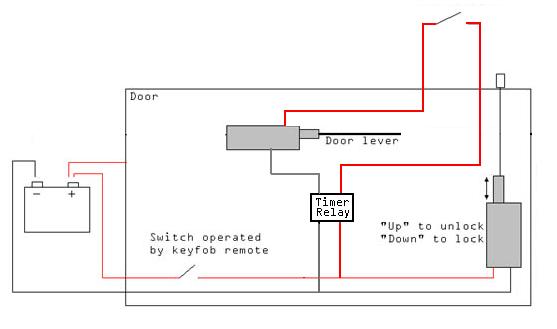
So how would this figure in my system, i have made a revised diagram, could anyone take time to look at it? This is evolving all the time, thanks for your ideas.

Door popping circuit - Page 2 -- posted image.

Hello!!!
Powermyster 
Silver - Posts: 962
Silver spacespace
Joined: April 06, 2005
Location: Ireland
Posted: July 22, 2005 at 8:51 AM / IP Logged  
 
 
use the DEI timer its worth waiting a few days for.
 
the maplins ones are little kits that you make i think.  the dei or similar are made for cars so go with something like that.
 
use everthing the way that you had it. but just take away the micro switch and use the relay instead.
 
 
look at the manual here is how to wire it..
 
Red  =  12V source
Black  =  ground
blackw/ stripe = unlock trigger
 
take way micro switch and attach wires to  Brown and Yellow   Orange will not be used....
 
set the relay to 20,30,40.....90 seconds whatever suits you
 
 
hope this helps
paulieA 
Member - Posts: 32
Member spacespace
Joined: July 21, 2005
Location: United Kingdom
Posted: July 22, 2005 at 8:58 AM / IP Logged  

that wont work i dont think.

If i just replace the microswitch with the relay. In the first diagram if you have a look, the popping circuit is not electronically linked to the unlocking circuit. The unlocking circuit makes the popping circuit active by physcially pushing the microswitch with the top of the solenoid. Sorry if this looks misleading.

The maplins ones come as a unit by the looks of it. Granted they are not as nice as the ones from radio shack, but the thing is they are £3 and the other ones are a lot more expensive...!

Would it not be correct in my second diagram? That is just a replacement for the microswitch as far as i can see it?

Hello!!!
Powermyster 
Silver - Posts: 962
Silver spacespace
Joined: April 06, 2005
Location: Ireland
Posted: July 22, 2005 at 9:05 AM / IP Logged  
i'm sure what i've just written will work.    the relay is replacing the switch.
 
your (-) unlock trigger off the alarm will trip the door unlock and the timer relay.
 
the circuit will then be completed for the preset length of time...
 
then you come alond and press your button. door pops open  voila
 
 
paulieA 
Member - Posts: 32
Member spacespace
Joined: July 21, 2005
Location: United Kingdom
Posted: July 22, 2005 at 9:10 AM / IP Logged  

yes, thats right, but by simply just replacing the microswitch with the relay wont work as that circuit is completly different to the unlocking circuit. They are only linked by the physical movement of the solenoid to push the microswitch. Do you gets me? Hard to explain.

If i was to simply swap the switch for the relay then the circuits would not be linked.

So id have to "tap into" the unlocking circuit as i have removed the previous method of "physical movement" which activated it.

So will my last diagram work, in theory? Im not too hot on electrics, and it took me forever to come up with my original microswitch design. Are all my earths and lives in the correct place in my new diagram?

Hello!!!
Powermyster 
Silver - Posts: 962
Silver spacespace
Joined: April 06, 2005
Location: Ireland
Posted: July 22, 2005 at 9:16 AM / IP Logged  
they will be linked electronically the way that i said..
 
the unlocking output from the alarm  tap into that with the black with stripe from the timer relay...
 
thats your link there.
 
you press the button the wire from alarm pulses (-) to the central locking Unlocking the door.
 
and because you've tapped into it it pulses (-) to the timer relay.  completing the other circuit...
 
 
i had a look at the other diagram. but didn't quite get it..  
paulieA 
Member - Posts: 32
Member spacespace
Joined: July 21, 2005
Location: United Kingdom
Posted: July 22, 2005 at 9:24 AM / IP Logged  

its confusing to show on a diagram coz its not actually like that in real life, but thats the only way i could explain it!

Right, by tapping into the unlocking circuit and placing the timing relay in there, that should work im thinking. I can set it to say 60 seconds before it clicks off and the button will not activate the door popping.

This is a very good idea, and just the type i was looking for. This way i can remove the unreliablity of having a physical switch, and replace it with an electronic device.

Would thatone from Maplins work? I mean its essentially the same thing as the one from radioshack. On-board timers, 2 inputs and an output with a N/O, N/C and a common?

Hello!!!
Page of 6

  Printable version Printable version Post ReplyPost New Topic
You cannot post new topics in this forum
You cannot reply to topics in this forum
You cannot delete your posts in this forum
You cannot edit your posts in this forum
You cannot create polls in this forum
You cannot vote in polls in this forum

  •  
Search the12volt.com
Follow the12volt.com Follow the12volt.com on Facebook
Monday, April 29, 2024 • Copyright © 1999-2024 the12volt.com, All Rights Reserved Privacy Policy & Use of Cookies
Disclaimer: *All information on this site ( the12volt.com ) is provided "as is" without any warranty of any kind, either expressed or implied, including but not limited to fitness for a particular use. Any user assumes the entire risk as to the accuracy and use of this information. Please verify all wire colors and diagrams before applying any information.

Secured by Sectigo
the12volt.com spacer
Support the12volt.com
Top
the12volt.com spacer